CURRENT PROBE
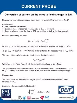
CURRENT PROBE. Conversion of current on the wires to field strength in SAC How can we convert the measured currents on the wires to Field strength in SAC? Assumptions : The wires radiate isotropic. Common mode impedance of a long wire is = 150ohms.

CURRENT PROBE
E N D
Presentation Transcript
CURRENT PROBE • Conversion of current on the wires to field strength in SAC • How can we convert the measured currents on the wires to Field strength in SAC? • Assumptions: • The wires radiate isotropic. • Common mode impedance of a long wire is = 150ohms. • Ground reflection from the floor in SAC can add up to 5 dB to the field strength. • From antenna theory we have: • Where: is the field strength, meter from an isotropic antenna, radiating Watt. • To get = 40 dBuV/m = 100uV/m in 3 meter distance, the needed power is = 3nW. • The current in the wire is calculated using the following equation: • With and the current is calculated to be 4.5 uA. • The ground reflection from the floor in SAC can increase the radiation level with up to 5 dB (1.77 times) worst case. The current in the wire must be lowered correspondingly. • Conclusion: • The current 3uA = 9.5 dBuA is set to give a radiation level of 40dBuV/m in 3 meter distance in SAC. • Conversion from current to field strength:
CURRENT PROBE RF Current Probe and radiated emission The RF current probe is here used in work with radiated emission in the frequency range 30-1000 MHz. The wires attached to a PCB module or whole apparatus act as antennas. If the common mode noise current in the wires are above a certain level the PCB or apparatus will probably fail the radiated emission test. The current probe can be used in 2 ways: • Method 1: • Relative measurement • The idea is that there is a correlation between the radiated emission measured in SAC and the noise current on the wires. This correlation can be used during the process of lowering the radiation from apparatus that has failed the radiated emission test in SAC. • Example of use: • The radiation level is found to be too high in SAC. Modifications must be made. • Place the product in a shielded room or in a place where the background noise is low. Use a nonconductive table. • Place the wires on the table much like they were in the SAC. • The common mode current on the wires are measured on the frequency where the problem was seen. Note the current level. • Do modifications to the product and measure the current again. You can quickly see the relative level of improvement. The wires must not be moved between the tests. • When the current level have dropped the wanted number of dB’s, do the test in SAC again. Often you will see an improvement in the same magnitude as you saw with the current probe. Method 2: Pre compliance test on a PCB or whole product. It has been investigated if it is possible to do a reliable prediction of the radiation in SAC, by measuring the common mode current on the wires connected to a module. 3 tests have been made on a PCB to investigate this.
CURRENT PROBE Method 2 – Test 1: The board is placed in SAC with all the wires connected. See Picture 1. The radiated emission measurement is performed. After the radiated emission test the current measurement is done on the setup in SAC. • Fig.1 SAC measurement (blue dots) compared with current probe measurement in SAC (red dots). • The estimation is quite good up to 500 MHz. • On frequencies < 100 MHz the radiated emission is lower than expected. The wires are short compared to the wavelength and radiates less than the antenna model used for the conversion. • On frequencies >500 MHz there are nearly no current on the wires but still a high radiation. The radiation comes from structures on the PCB, not from the wires. • . Picture 1. Current measurement in SAC. The current is measured on all critical frequencies on all wires with the current probe. The highest current is noted and converted to radiation with simple antenna theory. (3uA = 9.5 dBuA corresponds to 40dBuV/m @ 3 meter distance.) See the result in Fig. 1.
CURRENT PROBE Method 2 – Test 2: The PCB is moved to a shielded room with a wooden table. The setup from SAC is reconstructed as good as possible. See picture 2. • Fig.2 SAC measurement (blue dots) compared with current probe measurement in shielded room (red dots). • The result is not as good as the first. • The wires are not positioned completely in the same way they were in SAC. This gives a different common mode impedance in the wires and thereby a different current. • . Picture 2. Current measurement in shielded room. The setup is close to the one in SAC. The currents are measured again and converted to radiation. See the result in Fig. 2.
CURRENT PROBE Method 2 – Test 3: A long wire (3m) is connected to the main ground of the PCB and a cable (3m) is connected to one connector of the PCB at a time. The current is measured. The setup can be seen in Picture 3 and the result can be seen in Fig. 3 • Fig.3 SAC measurement (blue dots) compared with current probe measurement on long wires (red dots). • The result is bad. It is not possible to do a prediction with this very simple setup. • The setup for the current measurement must be closer to the one used in SAC during the radiated emission test. • . Picture 3. Current measurement with long wires.
CURRENT PROBE • Comments to the measurements: • Below 100 MHz it is not easy to spot the frequencies with the highest radiation in SAC, using the current probe. • High currents are seen on many frequencies, but there is only a high radiation on frequencies where the wires act as good antennas. • Moving the wires or making them a different length will shift the frequencies with high radiation. In the frequency range from 100-500 MHz a high current on the wires normally produces a high radiation in SAC. Unfortunately it is possible to have a low current on the wires and still have a high radiation in SAC. Fig 6. 4 peaks in the frequency range from 195-300MHz Fig 4. The 4 highest peaks from 30-100 MHz in SAC Fig 7. The spectrum of the current on the Power supply cable In the frequency range above 500 MHz only low currents were seen on the wires, even on frequencies with high radiation levels in SAC. When the PCB dimensions becomes bigger than λ/2 the radiation comes mainly from the structures on the PCB itself and not from the wires Fig 5. The spectrum of the current on The RS485 cable. Markers on the peaks.
CURRENT PROBE Conclusion Method 1: Relative measurement The RF current probe is a good tool to do relative measurements on failed products with. It is important to place the wires in a fixed position when measurements are compared. Preferably the wires could be place in the same way as they were during the radiated emission test in SAC. On frequencies where the PCB is bigger than λ/2 you will probably only seen very low currents on the wires and the method will probably fail. The main part of the radiation is coming from structures on the PCB itself. Use a loop probe to search for the fields instead. Method 2: Pre compliance test on a PCB or whole product. Doing accurate pre compliance testing with the current probe is difficult. The wire position alters the current in the wires a lot and makes the results uncertain. A quick and dirty pre compliance test of a module can be performed if the module is placed on a table with the wires in the same position as expected in the SAC. The common mode currents on all the wires are measured. The current should be below 9,5dBuA for the module to pass the 40 dBuV/m@3meter limit and below 16,5dBuA to pass the 47 dBuV/m@3 meter limit. At frequencies below 100MHz you will often pass the test with a higher current, because the wires are too short to form a good antenna. On higher frequencies you will sometimes fail the test with less than 9.5dBuA on the wires. The radiation is not only coming from the wires. Don’t expect to see any useful currents on frequencies where the module is bigger than λ/2.