Critical Current Probe
Team 16. Critical Current Probe. Interim Design. Amy Eckerle Andrew Whittington Philip Witherspoon. Sponsors. NHMFL Applied Superconductivity Center. The Project. Modify existing cryostat probe to conserve the amount of liquid helium used during a critical current measurement test.

Critical Current Probe
E N D
Presentation Transcript
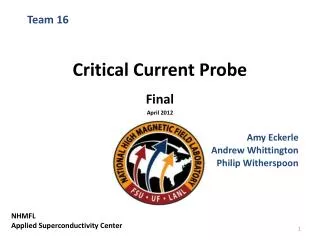
Team 16 Critical Current Probe Interim Design Amy Eckerle Andrew Whittington Philip Witherspoon
Sponsors • NHMFL • Applied Superconductivity Center
The Project • Modify existing cryostat probe to conserve the amount of liquid helium used during a critical current measurement test.
Objectives • Conserve Helium • Test 6-8 straight samples • 1 Spiral sample • Capability to deliver 1000 Amps to samples • Durable
Concepts Concept 1 – Heat Exchanger Concept 2 – HTS Leads Concept 4 – Reduce Leads Concept 5 – Fins Concept 6 – Gas Insulation Concept 7 & 3 – Casing/Spoke Design
Analysis on Original Probe • Give a base line to compare modifications • Need to find the heat transfer from room temperature to cryogenic level • Key attributes of probe needed: • Surface and cross sectional area • Temperature of starting and finish location • Length and number of leads (optimization) • Temperature dependant thermal conductivity • λ(T)
Conduction • Will cause the highest form of heat transfer • Very large temperature gradient
Convection • Helium gas traveling up through the probe will act as a heat exchanger. • Use LMTD method Higher temp Lower temp Flow of gas (assume constant temperature) Convection Coefficient
Convection Coefficient • Natural convection • Raleigh number (vertical plate) • Heat transfer coefficient (all ranges)
Radiation • Normally over looked, however at low temperatures will have noticeable affects. • Standard radiation equation • Reflectivity of material • Temperature difference holds biggest weight
Radiation shields • Use Stainless steel • Low emissivity • Low thermal conductivity • Put cylindrical plate around samples • Place circular plate near top of cryostat
Radiation shields (cont.) • Steel metal casing blocks most of radiation • Only radiation leak would be at the neck • Implementing a shield up top, cause more damage than good • Impractical
Copper Lead Fins • Increase convection • Fins will be used to cool the portion of the probe that is in the gaseous helium
Dimensions • The existing current leads have a rectangular cross section • The area will be increased with the use of fins • Not much extra room • Must optimize fins for the amount of area allotted 6.75mm 6.5mm Existing Current lead Cross section (mm)
Circular Fins 2.9mm • Easy to machine • Fit in given space • Need circular leads • Number of fins • Too many may not be helpful Cross section of a proposed circular copper lead
Fin Types • Tip conditions: • Convection heat transfer • Adiabatic • Constant temperature • Infinite Fin length • Can assume adiabatic – Not accurate • Convection from fin tip • Use corrected length
Convection from Fin tip • The corrected length, Lc, is used in place of the length, L, in the adiabatic equations • Each fin will need to be analyzed separately due to the changing temperature, T∞, through the system For circular fin Relation for the temperature distribution: Heat transfer rate:
Placement of Fins • To conserve helium: Need to cool the portion of the probe that enters the liquid helium • Used in the lower portion of the probe within the cryostat region above the liquid helium • Increase the heat transfer from the gaseous helium to the probe Possible design using circular fins
Casing/Spoke Design • Concept 7 – Spoke Design • Hard to implement • Simpler design • New Design • interrupts thermal conduction of the stainless steel tube • Easy to implement Previous Design New Design
Equations • k, thermal conductivity • Specific for material • A, is the area • T, is the temperature with respect to placement
Needed Information • Lower thermal conductivity allows thermal insulation • Thermal conductivity changes with temperature at cryogenic levels Theoretical temperature profile With G10 Length
Stainless SteelThermal Conductivity as a Function of Temperature
Calculation Steps • First find the rate of heat transfer • Then, using this find temperature at different values of x • Can make this a function of length to plot • Can plot without G10 portion vs. with G10 to measure effectiveness
HTS leads • High temperature superconducting leads • Conducts current orders of magnitude greater than copper • Poor conductor of heat • Reduces surface area of copper • Removes copper from entering liquid helium bath
Existing Probe Copper current leads for existing probe Top flange made of G-10 Stainless steel casing G-10 sample holder
Existing Probe The current leads for existing probe
Remove section of copper lead Replace with HTS material Solder joint
G-10 Structural support Remove section of copper lead HTS material
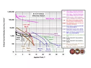
HTS Design • Amount of current that is passed through HTS lead depends on: • Temperature • Applied field
Needed Information for HTS Leads • Temperature profile of cryostat • Placement for HTS leads • Field profile from magnet • Layers of HTS required for 1000 Amps of current • Heat transferred from HTS lead
Heat Exchanger cap • Reduce the temperature gradient in copper leads • Complexity of cap poses problem • Substitute with extension of leads
Gas insulation • Would be hard to manage due to maintaining temperature difference. • HTS (High Temperature superconducting) leads already decided
Optimization of Leads • Reducing the number of leads • Less heat transferred but more tests that would need to be done. • C is the number of tests • x is the number of leads • a is the heat transfer rate of one lead • h is any helium losses independent of leads • Q is total heat transferred.
Accepted Concepts • Concept 2 – HTS Leads • Great reduction in copper surface area • Prevents copper leads from entering liquid helium bath • Concept 4 – Reduce Leads (Optimization) • Optimization is a necessary part of probe design
Rejected Concepts • Concept 6 – Gas Insulation • With accepted HTS becomes impractical
Further Calculation • Concept 1 – Heat Exchanger • Heat exchanger effectiveness • Equivalent length to replace heat exchanger • Concept 5 – Fins • Type of fin • Frequency / fin efficiency • Concept 7 & 3 – Casing/Spoke Design • Compare heat transfer of as is casing with G-10 insert