Download

1 / 28
280 likes | 396 Views
(non-)Destructive high-rate tests on silicon strip modules. Emulating LHC beam incidents using the PS booster and measuring the effect on a LHCb Velo silicon strip module Lars Eklund, on the behalf of the LHCb Collaboration. Outline. Introduction Motivation and previous publications

E N D
(non-)Destructive high-rate tests on silicon strip modules Emulating LHC beam incidents using the PS booster and measuring the effect on a LHCb Velo silicon strip module Lars Eklund, on the behalf of the LHCb Collaboration
Outline • Introduction • Motivation and previous publications • The participants • The PS booster and the LHCb/VELO module • The measurements • Observables and program • The surprise • Results and interpretations • Summary L. Eklund, Vertex 2009
Motivation (1) The LHC • Stored beam energy 102 - 103 times larger than any previous accelerator • New machine, limited operational experience The LHCb Velo • Very close to the beam: silicon sensors @ 7-30 mm distance (moving!) • Located next to the injection line TI8 • Designed and built: but operation procedures can be changed • LV & HV on/off at injection? • Feedback to the machine • Intensity limit at injection • Currently H/W 1011 protons and F/W 1010 L. Eklund, Vertex 2009
Motivation (2) Possible beam incidents • Injection failures: • incomplete or unsynchronized kicker fire => mostly Alice & LHCb • wrong magnet settings in transfer line => mostly Alice & LHCb • wrong magnet settings in the LHC => everybody • Circulating beam failures: (mostly caught by collimators) • magnet failure / mishap => everybody • RF failure => everybody • collimator failure / mishap => everybody • Extraction failures: • Under-kick, unsynchronized beam dump => mostly CMS L. Eklund, Vertex 2009
Previous studies • Atlas silicon strip sensors: LASER (2 types) • IEEE Trans. Nucl. Sci. NS47 (2000) 1902 • Voltage across AC coupling vs. RRC &CRC • Atlas silicon strip: 1064 nm LASER (1 W) • NIM A 541 (2005) 15-20 • Beam spot 8 µm, 10 ns pulse, 109 MIP equivalent • Damage: HV bias > 200 V @ 109 MIP (on one strip) • CMS silicon strip: 24 GeV protons (CERN/PS) • NIM A 518 (2004) 328-330 • Beam spot 10x3 cm2, 42 ns bunch, 2 bunches of 7x10¹⁰ protons • No damage • Atlas pixel: 24 GeV protons (CERN/PS) • NIM A 565 (2006) 50 • Beam spot 6x3 cm2, 42 ns bunch, 8 bunches of 1x10¹¹ protons • No damage L. Eklund, Vertex 2009
The PS booster Resto2 Main bldg L. Eklund, Vertex 2009
The beam line Proton beam with 1.4 GeV energy • Intensity: 2x10⁹ – 9x10¹² p • Beam spot: 5 mm (max 4x10¹³ p/cm2) • Bunch length: ~200 ns • Cf. tests in the PS: max 3x10¹⁰ p/cm2 Compare with LHC • Pilot bunch @ injection: 2x10⁹ protons (450 GeV) • 300 µm beam spot • 0.4 ns bunch length • Full luminosity (L=1034) SPS injection train • 288 bunches of 1011 protons • 4x10¹³ protons/cm2/bunch L. Eklund, Vertex 2009
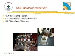
The set-up • Module mounted close to the beam dump • Back-splash gives non-negligible dose • Rough estimate of dose: 1013 neq & 1 kGy (very preliminary) • Small scale experiment L. Eklund, Vertex 2009
The victim • LHCb/Velo spare from production • Double sided (R & Phi sensors) • 2048 AC coupled n-on-n strips / side • 16 FE chips (IBM 0.25 µm) • Mounted in the beam line • Cooled to +1 ˚C (LV on) • Florescent screen to view the beam • Insert/retract from beam line • Remote control and read-out L. Eklund, Vertex 2009
FE inputs (2048 channels) Vfp LV (VDD) VDD bonds (16x4) protection diodes CFB CLV CG bond wires pre-amp GND bonds (16x5) LV (GND) GND probe Al RC filter Rbias 10 pF SiO2 CAC 10 MΩ HV return (GND) n n+ Osc. GND QRC QRC 10 pF RDET CDET CRC CRC 10 MΩ 22 nF RRC HV probe RRC 1 kΩ HV bias (-300V) p+ Electrical model – static case CDET = 1 nF/2048 ch. RDET = 1-100 MΩ/2048 ch. CAC = 250 nF/2048 ch. Rbias = 1 kΩ x 2048 ch. CRC = 10 nF RRC = 5 kΩ CFB = 400 fF (per ch.) CG = 10 pF (per ch.) CLV = 32 x 100nF
The measurement sequence - observables • Intensity steps: 2x10⁹, 2x10¹⁰, 2x10¹¹, 2x10¹² & 9x10¹² • Each step: LV/HV off, LV on/HV off, LV on/HV 150 V & LV on/HV 300V • Each beam ‘shot’ follows the same pattern • A set of standard measurements • I/V of both sensors • Noise & pedestal data • Test pulse data at +1.5, 0 and -150 V (for some shots) • Insert the module, acquire during the shot • 14 consecutive triggers of front-end data • Voltage on hybrid GND and sensor bias via oscilloscope • Beam spot image via a a camera • Repeat the same set of measurements • Shots on two sensor positions • Shots on five front-end chips (only LV on/off matters) • No measurable damage up to • 9x10¹² @ 300V bias on the sensor • 2x10¹¹ (LV on) on the FE chips L. Eklund, Vertex 2009
Beam images Combined R-Φ sensor front-end data Beam line camera on scintillating screen L. Eklund, Vertex 2009
I/V curves • I/V curves in-situ between each shot • Superimpose temperature corrected I/V curves • Small increase probably due to accumulated dose • Rough estimate between first and last curve: 3x10¹² neq & 200 Gy • Work in progress • Correlate with radiation monitoring data L. Eklund, Vertex 2009
Thermal image: No hot-spots The majority of the shots hit this area L. Eklund, Vertex 2009
Noise & Pedestals • Noise & pedestals measured in-situ between each shot • Plots show date taken towards the end of the program • No change visible • Detailed analysis is in progress L. Eklund, Vertex 2009
Test pulse response – post-zap • Test pulse response • ‘booster’: in-situ after a few shots at 2x10⁹ • ‘lab’: lab measurement after the full program • Gain difference due to different analogue drivers/receivers • Bad channels identical to production QA L. Eklund, Vertex 2009
vivum HV bias reduced to 0 V Post-mortem – why did it survive? • Deposited energy (in 300 µm Si) • 9x1012 x 24 k MIPs x 3.6 eV = 1.2 Joule / 200 ns • Temperature increase in 1 cm2 Si: 2.5 ˚C • Maximum SPS injection train (288x1011): 4 Joule / 10 µs • Local energy store: the RC filter • 10 nF @ 300V => 0.5 mJ • Absorption volume critical • Massive ionisation in biased silicon • QRC(300V) = 3 µC • Deposited charge @ 2x10⁹: 7.5 µC • Possible transient damage • Current through front-end • AC coupling diode • Voltage on front-end input • Fast HV ramp-down L. Eklund, Vertex 2009
time [µs] Voltage across the sensor vs. time • Oscilloscope measurements • Hybrid GND • Backplane • 1 sample / ns • Ground reference arbitrary • Huge ground bounce • Large pick-up • Plot Vbackplane-VhybridGND • Two distinct features • Sharp rising edge (50 ns) • Slow charge-up L. Eklund, Vertex 2009
time [µs] The first 50 ns … 6 GV/s 2.5 GV/s 2 GV/s L. Eklund, Vertex 2009
VDD bonds (16x4) FE inputs (2048 channels) Current during the discharge CG bond wires Divided between 2048 inputs and 80 GND bonds CLV pre-amp VIN protection diodes IZ/2048 GND bonds (16x5) Rbias reduced to ~100kΩ/2048 via punch-through mechanism Still to large to play a role RIN IGND = IZ/80 Al RC filter Rbias SiO2 VAC CAC QRC transferred to CAC n n+ QRC = 3 µC IZ CDET CRC = 10 nF IZ RRC p+ Electrical model – the first 50 ns … • VIN = IZ/N x RIN • N is large (~ 2048) • RIN is small (~Ωs) Ramping 300 to 0 V in 50 ns seems to be OK! L. Eklund, Vertex 2009
Shots on the FE chips • 56 shots on the FE chips: 2x10⁹ – 2x10¹¹ • No destructive latch-up • Design rules include structures to prevent latch-up • Seems to be effective! • SEU analysis in progress: none observed so far • Requires large energy deposited in small volume • Nuclear reactions necessary • Cross-section very low • Triple-redundant registers: corrected every 2 ns L. Eklund, Vertex 2009
Summary • The PS booster provided beam to emulate LHC beam incidents • 200 ns shots, 2x10⁹ to 9*1012 protons • A VELO strip module was subject to a large number of shots • Two positions on the sensor, five FE chips • Survived 9x10¹² protons on sensor with 300 V bias • Survived 2x10¹¹ protons on the FE chip • No visible change in performance • I/V curves, noise, pedestals, thermal imaging, … • Saving graces • The whole sensor responds as a unit • Large area sensor – many channels • CAC >> CRC (+CDET) • Protection diodes on the FE inputs • Triple-redundant registers in FE chips • Analysis & measurement still in progress L. Eklund, Vertex 2009
Back-up slides L. Eklund, Vertex 2009
B0 B1 B2 B3 B4 B5 B6 B7 63 shots on the sensor 56 shots on the FE chips Total number of shots Shots on the sensor (position 1+2) Shots on the front-end chips L. Eklund, Vertex 2009
“FWHM” of beam ~80 strips of 70 mm pitch ~5.5 mm Beam size – seen by the Φ-sensor Response to beam during initial 25 ns of beam rising edge in f detector L. Eklund, Vertex 2009
Fitting rising edge of all shots • Termination of HV monitoring signal was improved during the program • Rising edge not affected by termination • 150 V: Shots 3-5 & 24 @ 2e9, shot 10 @ 2e10 and shot 14 @ 2e11 are less than 1 GV/s • 300V & 9e12: Shots 34, 42, 44 are greater than 5 GV/s • Weak correlation with intensity & voltage • Large shot-to-shot variation L. Eklund, Vertex 2009
Re-charge of HV … • Average time constants • τ = 6.8 μs @ 2e9 & 150V • τ = 13 μs @ 9e12 & 150V • τ = 10 μs @ 9e12 & 300V • Need spice simulation to understand recovery times • Re-charge depend on intensity • Some long term (10μs) process in the sensor? L. Eklund, Vertex 2009
Decay-time of all available wave forms • Falling edge clearly affected by the termination • Not possible to compare the two data-sets • De-convolution of impulse response maybe possible L. Eklund, Vertex 2009