Download

1 / 15
150 likes | 168 Views
This article provides a detailed description of the construction, production, and quality assurance processes involved in creating the ATLAS SCT Endcap Modules for the Large Hadron Collider. It also discusses the challenges faced and the current status of the project.

E N D
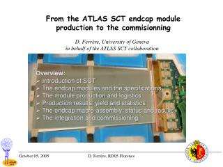
Construction of the ATLAS SCT Endcap Modules Steve Snow Manchester University On behalf of the ATLAS SCT Collaboration • Context - ATLAS, Inner Detector, Silicon strip tracker (SCT) • Module description - design choices • Module production - collaboration, philosophy, flow of components • Module QA - specifications • Use of production database - technical, organisational • Assembly procedures, test procedures • QA results - electrical and mechanical • Production rate and yield • Lessons learned • Where are they now ? - wider view of SCT status
LHC, ATLAS, ID, SCT • ATLAS is one of the two general purpose detectors under construction at the Large Hadron Collider. • The inner detector, situated in a 2 Tesla field, comprises three silicon pixel layers, four silicon strip layers (SCT) and many "straw" drift chambers forming the transition radiation tracker (TRT). Each SCT endcap consists of 9 discs, each disc populated with up to 132 modules. • Main challenges for the SCT: • Radiation dose ~ 3x10¹⁴ protons/cm² over 10 years. • Radiation only tolerable if silicon is always kept cold (-7 C). • Bunch crossing interval 25 ns; require good rejection against events from neighbouring bunch crossings. • Only 4 layers; must have high (~99%) efficiency per layer to get high track-finding efficiency. • Support, power, cool, readout SCT with minimal space,X0. ATLAS overview Present status in cavern Inner detector layout
Endcap modules description Hybrid Optical clock/control and readout. reduce cross talk between modules ABCD3T readout chips. Atlas Binary Chip in DMILL v3 with Trim-DAC. 128 channels x 12 chips noise ~1500 e before irradiation, ~1800 e after. Pair of detectors chained to make 12 cm strip. Limit is two because of - Noise ( capacitive load on readout front end) Occupancy in jets. Tiling efficiency of disc Silicon detector. 6x6 cm2 768 x 80 mm p in n strips ( ~22 micron resolution) 40 mrad stereo angle between front and back detector pairs. Flex circuit. Six layer copper-kapton circuit wrapped around ... Substrate. carbon fibres in carbon matrix. High strength with high thermal conductivity. Spine. Support and cool detectors TPG (graphite). Mechanically weak. very high thermal K Aluminium nitride. Strong. Similar c.t.e. to silicon Fan-in. Electrical connection and thermal isolation between detectors and hybrid. Detectors must be cold, hybrid less critical.
Endcap module production collaboration Fourteen institutes: 11 universities + 3 (small groups from) large labs Typical group: 6 academic + 3 technical Collaboration developed SCT endcap over 10 years, then transformed itself into a production line for 2 years. Three clusters. Variable level of specialisation. Philosophy:Carefully define and agree final QA tests, upload QA results to public database daily, leave institutes flexibility to choose how they achieve good results. Institute qualification - given 5 sets of production components, make at least 4 modules fully in spec.
Electrical specifications • Less than 1 % dead channels ( 15/1536 ) • Noise occupancy at 1 fC less than 5x10⁻⁴ • Detector current at 350 V less than 20 mA per detector. • Operation for 24 hours cold. ( thermistor on hottest part of hybrid at ~10 C) ABCD3T chip. Binary readout with built-in charge injector. Scan threshold at constant charge and plot occupancy; S-curve mid-point is response and width is noise. Response versus charge gives gain and offset. Trim DACs allow offset to be adjusted channel-by-channel. Trim all channels to give same response at 1 fC. Mask dead* channels. Set threshold to 1fC and do high statistics run with no injected charge to find noise occupancy. * dead = high noise, low gain or very outlying offset value, low noise.
Mechanical specifications Thirteen parameters define the positions of detectors and location holes in the XY plane. Critical tolerances: detector angles; a1-a4,stereo ± 0.13 mrad detector front-back alignment; midyf ± 5 microns location holes; mhx,mhy,msy ± 20 microns Z level of detector surface relative to mounting block surface is measured on a grid of 5x5 points per detector. All points must be within 875 ± 115 microns (front) or -375 ± 115 microns (back). These XY & Z tolerances define modules that are as close to perfect as makes no difference. In practice we were able to increase some tolerances by 50% to define a "pass" category, while keeping within the physics spec. Physicist - "what is the r.m.s. of all midyf values?" Engineer - "is this module in or out of spec ?" • Other specifications: • Must survive 10 thermal cycles from -30 to +35 C and remain in tolerance. • Envelope to avoid clashes ( blue squares) • Integrity of ceramic on mounting surfaces.
Database Structure Implementation Uses Keep track of whereabouts and status of all components. Record all test results in a standard format. Java extraction and ROOT display; many nice plots of individual modules, overall progress & trends. Encourages (self-)discipline, openness, early revelation of problems. Consensus: A module does not exist until it is recorded in the DB. It is not a good module unless all test results are in the DB and in tolerance.
part manual, part automated Assembly procedure 2. Dispense glue on both sides of the spine, while it is supported in a frame. Place one pair of detectors on one side of the spine. 1. Align a pair of detectors using XYq stages under measuring microscope. Pick up the pair together on a single vacuum chuck. Repeat for another pair. 4. Cure glue. Use similar procedure with less accuracy to attach hybrid and fan-ins 3. And the other pair on the other side, making a detector-spine-detector sandwich. 5.Position whole module on vacuum chuck and wire-bond both sides.
Electrical test procedures Mount module in cooled test-box. Six test-boxes in one isolated enclosure, read out through VME to PC. Set of ROOT macros using C++ dll to run and analyse tests. Run for 24 hours with clock and triggers. Every 2 hours do "confirmation test". At end do "characterisation test" and I-V scan up to 500 V. Save all results in DB. 24 hour test of 5 modules Set of custom modules in VME SLOG. Generates slow control commands. AERO. Emulates the optical interface by encoding the clock and commands in one BPM carrier for transmission to the module. Mustard. Receives, stores and decodes data from the module. SCTHV a prototype HV supply for the SCT. SCTLV a custom designed low voltage supply for the SCT. Bare detectors, summed After module assembly After wire-bonding and thermal cycling Typical result of I-V test at three stages in production
Mechanical test procedures thermal cycle (-30 to +35) x10 with humidity < 70% Survey module on optical CMM. Before After Z profiles Survey again. Typical result; no measurable change (<1 micron) in-plane (XY) small changes (~10 microns) out-of-plane (Z)
Electrical QA results Number of dead channels in the module. Specification was 15 channels (<1%).Shortage of perfect chips: hybrids built with two 1-bad-channel-chips to spread the loss uniformly. Average 2 extra dead channels introduced in bonding. Module leakage current (mA) at 350V. Specification was 20mA per detector, i.e. 80mA for a long module. Typical modules are very far below this limit. Failures usually due to obvious mechanical damage. Noise (ENC electrons) Not subject to a QA specification but an indicator of electrical performance. Two peaks due to 6 cm and 12 cm strip lengths. Module occupancy at 1fC after masking dead channels. Specification was 5x10⁻⁴.Essentially no modules fail this test once noise originating from the test equipment has been eliminated.
Mechanical QA results midyf (mm). Specification < 5 mm, pass < 8 mm. Alignment of front detector pair relative to back pair, in direction perpendicular to strip. mhy (mm). Specification < 20 mm, pass < 30 mm. Alignment of module location hole relative to detectors, in direction perpendicular to strip. zminf (mm). Specification >0.76 mm, pass > 0.71 mm. The lowest of the 50 points measured on the front surface of the module, relative to the mounting block. stereo (mrad). Specification -20 ± 0.13 mrad. Stereo angle between front detector pair and back pair.
Production rate and yield Rate builds up slowly as assembly sites become qualified. From May 2004 to June 2005 rate is about 40 modules / week. Rate tails off as sites reach their quota. Target is 1976 + 5% spares. Yield starts around 70% in learning phase. Climbs as experience is gained and later production comes to dominate the average. Near-final statistics: 2367 started, 2290 finished, 1993 good, 140 pass, 104 hold, 53 fail. Yield (good+pass) 93 % . Losses Project plan Actual Module assembly 15% <7% Mounting on discs 5% <1% so far Reasons for losses Detector current ; 10 % Dead channels ; 20 % YX metrology ; 35 % Z metrology ; 30 % Other ; 5%
Lessons learned A large scale (~2000 module) production carried out by a collaboration of many small institutes was successful. Loss of components (~7%) was about a factor 2 lower than allowed for in planning. Module quality was high and consistent with expectations from the R&D phase; no new performance problems appeared in the production phase. With a distributed collaboration like this communication is the key; weekly email reports, weekly phone meetings and the production database. Measure progress by what is in the database; gives powerful tool to project coordinators. Automation was only used in places were it was easy to implement. It gave no problems. Much was done by hand. Losses were due to many different errors, each one rare. If using good tools, people are reliable and seldom make the same mistake twice. Despite a lot of shipping, only a few modules were damaged in transit. The total time spent on each module (component QA, assembly, wire-bonding, testing, packing, shipping and database entry) was around 20 hours. The picture painted in this presentation is a bit too rosy. Many problems in the last two years looked as if they might stop us.
Where are they now ? Endcap C (Liverpool). All modules are mounted on their discs. Discs 9 to 5 are inserted in the support cylinder. Inserting the remaining discs, connecting services and testing is expected to complete this year. Shipment of endcap to CERN planned for January. Endcap A (NIKHEF). Discs 9 to 6 equipped with modules. Disc 9 inserted into cylinder. Shipment to CERN planned for early next year. All modules so far mounted on disc or barrel can be read out. Module noise in-situ is the same or lower than in test box. SCT Barrel. The last of the four barrels was shipped from Oxford to CERN a few weeks ago. Next steps: integration of the 4 barrels, insertion into the TRT.