NON DESTRUCTIVE TESTS
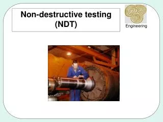
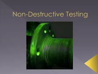
NON DESTRUCTIVE TESTS. FLOODED MEMBER DETECTION. Flooded member detection is an inspection method which is utilized for analyses of offshore steel structures, where pipe sections are used.


NON DESTRUCTIVE TESTS
E N D
Presentation Transcript
FLOODED MEMBER DETECTION Flooded member detection is an inspection method which is utilized for analyses of offshore steel structures, where pipe sections are used. These structural elements (Members) are analysed for possible lack of water resistance which may indicate water leakage at the weldings, which are then selected for closer inspection. The method today is mostly undertaken by the use of ultrasound, if and when divers are used. This however requires a "living" A-scan in order to be useful and so a radioactive source is instead used when ROV (Remote Operated Vehicle) are used for inspection purposes. Through development of the inspection equipment it will be possible to also use ultrasound for ROV. This entails the improvement of safety and handling of ROV in comparison with the use of radioactive sources. The interest in such equipment which uses ultrasonic waves for ROV purposes is significant among many international underwater equipment operators. The result of the project will be presented to all interested parties at a seminar organized by Force and OCD.
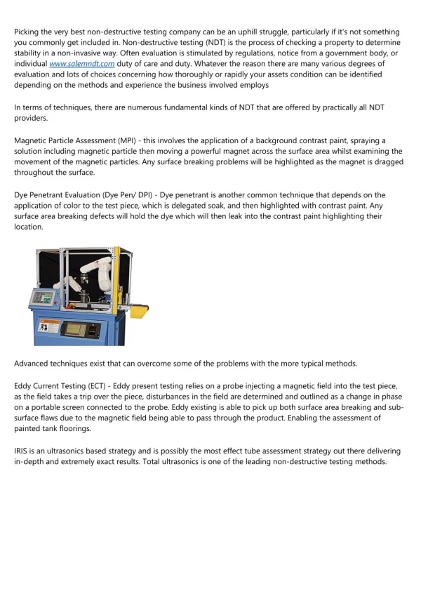
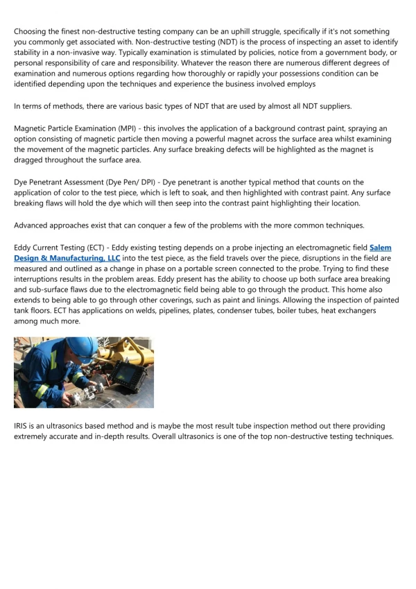
To assess the integrity of the pipe and casing an ROV deployed flooded member detector is deployed. This device has a small radioactive source and Geiger counter mounted on a fork. The counts are proportional to the average density of whatever is between the forks and thus interrupts the radioactive beam. See Figure. Flooded Member Detector. The detector is calibrated on the west flowline, which is believed to be dry.
This system is available for use with either Diver or ROV operation. Diver System: 0.5 Mhz Subsea Transducer 200Metre Umbilical Ultrasonic Electronics Rugged Lap top Computer RSL FMD Software Ultrasonic Output RS232 Range 0.5mtr to 10mtr Power 110/240volts ROV System: 0.5 Mhz Subsea Transducer Subsea Electronic Pod Dimensions 200 x 75mm Rugged Lap top Computer RSL FMD Software Power to Subsea Electronics 24vDC Output RS485 Range 0.5mtr to 10mtr Depth rating 4000 Meters.
Field-proven flood member detection techniques, integrated within the concept of health monitoring, offer an alternative to underwater nondestructive testing methods based on ultrasound and x-rays, which have been used to detect the presence of seawater in these applications, often with diverse or remote operating vehicles. The system employs a single piezoelectric transducer which can be permanently attached to the inner wall of every sub-sea structure and which is powered by a normally inert seawater battery. Upon activation, the sensor transmits ultrasonic chirp or tone encoded pulses, in the range of 21–42 kHz, to a monitoring receiver system at deck level for decoding and identifying flooded members.
Welds discontinuities • Gas Pores (Πόροι αερίου) • Slag inclusions/entrapments(Εγκλείσματα σκουριάς/Παγίδευση) • Incomplete fusion and penetration(Ατελής τήξη και διείσδυση) • Cracks(Ρωγμές) • Elongated • Transversal • Asteroid
NDT INSPECTION • Visual Inspection • Liquid Penetrant Inspection • Ultrasonic • Straight beam • Angle beam • Magnetic Particles Inspection • Radiographic Inspection For the below type of defect-imperfection which type of NDT method is suitable to complete tests. Fill the below matrix with the indication (0) to (3). (0)= Does not detect (1)= Not indicated (2)= Indicated (3)=Ideal for implementing
Two dimensional surface Three dimensional surface Two dimensional close to surface Two dimensional close to surface and parallel to it Type of defect – imperfection Internal two dimensional vertically to surface Three dimensional close to surface Internal two dimensional parallel to surface Internal three dimensional
(0)= Does not detect (1)= Not Indicated (2)= Indicated (3)= Ideal for implementing
Table presents the ability of all aforementioned methods of the NDT in detecting and identifying imperfections – defects. The Ultrasonic method compared to the aforementioned, presents important advantages. The high penetrating capability, the high clearness, the applicability to all materials, as well as the ability to use mobile devices making it one of the most widespread methods of the NDT. It seems that the ultrasonic method has the ability to give answers to all kinds of defects – imperfections. However, the ultrasonic method with a straight beam shows that it can’t give answers to every type of two dimension defects – imperfections, such as cracks. In this case the test is completed using an ultrasonic with an angle beam, which gives satisfactory results in all occasions.
QUALITY LEVELS • LOW (D) SUM <30% T nominal • MEDIUM (C) SUM <25% T nominal • HIGH (B) SUM<20% T nominal FOR ALL THE ABOVE LEVELS THE DEFECT MUST NOT EXCEED 10mm
Composite MaterialsDefects - Imperfections • Structural • Geometrical • Aesthetical
Voids • Wrinkles • Fiber reinforcement defects • Geometrical defects • Delaminations • Dry zones-spot • Inclusions