Systematic Absences
Systematic Absences. The presence of translational symmetry elements and centering in the real lattice causes some series of reflections to be absent – we will deal with this in more detail when we look at structure factors.

Systematic Absences
E N D
Presentation Transcript
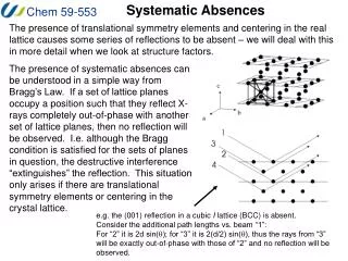
Systematic Absences The presence of translational symmetry elements and centering in the real lattice causes some series of reflections to be absent – we will deal with this in more detail when we look at structure factors. The presence of systematic absences can be understood in a simple way from Bragg’s Law. If a set of lattice planes occupy a position such that they reflect X-rays completely out-of-phase with another set of lattice planes, then no reflection will be observed. I.e. although the Bragg condition is satisfied for the sets of planes in question, the destructive interference “extinguishes” the reflection. This situation only arises if there are translational symmetry elements or centering in the crystal lattice. e.g. the (001) reflection in a cubic I lattice (BCC) is absent. Consider the additional path lengths vs. beam “1”: For “2” it is 2d sin(q); for “3” it is 2(d/2) sin(q), thus the rays from “3” will be exactly out-of-phase with those of “2” and no reflection will be observed.
Systematic Absences These systematic absences (or “systematicextinctions”) thus indicate the presence of centering and/or specific symmetry elements in the lattice and provide us with information about the space group of the crystal. Note that in the International Tables, the “limiting conditions” for reflections are reported – this is the opposite of a systematic absence – so be careful in interpreting the information. Note that the conditions for reflections or absences are reported as simple equations in which “n” indicates any integer. E.g. if for reflections of the type (h00), h = 2n + 1 are absent (this means that if h is odd, then the reflection will not be observed) Conversely, this means that the limiting condition for such reflections to be observed is: for (h00), h = 2n (i.e. reflections are only observed when h is even) E.g. for C centered cells, such as the one pictured above, (hkl) reflections are systematically absent when: h + k = 2n + 1 (if the sum of h and k is odd)
Systematic Absences Because certain symmetry elements cause absences that supersede those caused by other elements, it is necessary to search for the presence of symmetry elements in the following order: first search for unit cell centering, then for glide planes, then for screw axes. The reason for this becomes apparent upon examination of the conditions listed below – note there are some more conditions that are found in the hand-out for today. Symmetry Element reflection absence conditions A centered Lattice (A) hkl k+l = 2n+1 B centered Lattice (B) h+l = 2n+1 C centered Lattice (C) h+k = 2n+1 face-centered Lattice (F) hkl h+k = 2n+1 h+l = 2n+1 k+l = 2n+1 Body centered Lattice (I) hkl h+k+l = 2n+1
Systematic Absences Symmetry Element reflection absence conditions Glide Perpendicular to a translation b/2 (b) 0kl k = 2n+1 c/2 (c) l = 2n+1 b/2+c/2 (n) k+l = 2n+1 b/4+c/4 (d) k+l = 4n+1 Glide Perpendicular to b translation a/2 (a) h0l h = 2n+1 c/2 (c) l = 2n+1 a/2+c/2 (n) h+l = 2n+1 a/4+c/4 (d) h+l = 4n+1 Glide Perpendicular to c translation a/2 (a) hk0 h = 2n+1 b/2 (c) k = 2n+1 a/2+b/2 (n) h+k = 2n+1 a/4+b/4 (d) h+k = 4n+1 21-fold screw a h00 h = 2n+1 42-fold screw along b 0k0 k = 2n+1 63-fold screw c 00l l = 2n+1
Reciprocal Lattices Overall, the combination of the symmetry of the reciprocal lattice and the presence or absence of certain types of reflections is used to determine the space group of the crystal lattice. In practice, the identification of systematic absences is done by the collection software on the diffractometer and you will rarely have to look at the results yourself. Note that in many cases the systematic absences are not enough to differentiate between alternative space groups (e.g. Cc and C2/c) so one must solve the structures and assess the final results using statistical methods. We will look at this and also examine systematic absences in the context of structure factors later in the course. Remember that reciprocal lattices are 3-dimensional and you might have to look in different layers to find the absences.
The Ewald Sphere We have constructed the reciprocal lattice (RL) in terms of the reciprocal d-spacings, 1/dhkl, another utility of this lattice in terms of crystallography is made apparent by the Ewald sphere, which tells us the angle at which each family of planes will diffract! Consider a circle of radius r, with points X and Y lying on the circumference. If the angle XAY is defined as q, then the angle XOY will be 2q by geometry and sin(q) = XY/2r If this geometry is constructed in reciprocal space, then it has some important implications. The radius can be set to 1/l, where l is the wavelength of the X-ray beam. If Y is the 000 reciprocal lattice point, and X is a general point hkl, then the distance XY is 1/dhkl Thus: sin(q) = (1/dhkl)/(2/l) or, rearranged: l = 2 dhkl sin(q) , and Bragg’s law is satisfied!
The Ewald Sphere This means that when a lattice point intersects the Ewald sphere, the reflection corresponding to that family of planes will be observed and the diffraction angle will be apparent. The step-by-step construction and initial use of a Ewald sphere is described on the web site (http://www.doitpoms.ac.uk/tlplib/reciprocal_lattice/ewald.php). Starting with an indexed reciprocal lattice, an incident X-ray beam must pass through the origin (000) point, corresponding to the direct undiffracted beam of X-rays.
The Ewald Sphere The Ewald sphere for this case is defined by making a sphere of radius 1/l having its diameter on the X-ray beam that intersects the origin point. In the diagram on the left, no other RL points are on the surface of the sphere so the Bragg condition is not satisfied for any of the families of planes. To observe reflections, the reciprocal lattice must be rotated until an RL point contacts the surface of the sphere. Note: it would be easier to rotate the sphere on paper, but in practice, we rotate the crystal lattice and the RL.
The Ewald Sphere When a reciprocal lattice point intersects the Ewald sphere, a reflection will occur and can be observed at the 2q angle of the inscribed triangle. To be able to collect as many different reflections as possible, it is thus necessary to be able to rotate the reciprocal lattice to a great extent… You can see how this works at: http://www.doitpoms.ac.uk/tlplib/reciprocal_lattice/ewald.php
The Ewald Sphere Our need to rotate the crystal in numerous ways to bring all of the families of planes into reflection (i.e. to make RL point intersect with the Ewald sphere) explains the design of the goniometer portion of the diffractometer. The 4-circles of the goniometer allows the crystal to be rotated in virtually any direction while remaining in the X-ray beam. The labels for each of the goniometer axes (f, c, w, and q) are indicated on the diagram below. Note that there are different designs (such as the Kappa geometry) that accomplish the same task.
The Ewald Sphere If one rotates the Ewald sphere completely about the (000) reciprocal lattice point in all three dimensions, the larger sphere (of radius 2/l) contains all of the reflections that it is possible to collect using that wavelength of X-rays. This construction is known as the “Limiting sphere” and it defines the complete data set. Any reciprocal lattice points outside of this sphere can not be observed. Note that the shorter the wavelength of the X-radiation, the larger the Ewald sphere and the more reflections may be seen (in theory). The limiting sphere will hold roughly (4/3pr3/ V*) lattice points. Since r = 2/l, this equates to around (33.5/ V*l3) or (33.5 V/l3) reflections. For an orthorhombic cell with a volume of 1600Å3, this means CuKa can give around 14,700 reflections while MoKa would give 152,000 reflections.
The Ewald Sphere Remember that the reciprocal lattice can also be defined in terms of the wavelength of the X-radiation (by setting K = l). In such a construction, the Ewald sphere remains the same size, having a radius of 1 (l· 1/l = 1), independent of the wavelength. Such pictures show the increased number (and density) of reflections for the shorter wavelength radiation. As noted previously, this means that longer wavelength radiation might be necessary to resolve individual reflections for crystals with large unit cells and small reciprocal unit cells. short l long l To see many of these effects, get XrayView (http://phillips-lab.biochem.wisc.edu/software.html).
Cell Volume, Density and Z The final goal of the crystallographic experiment is to determine the arrangement and position of the contents of the unit cell and thus the structure of the crystal. To this point, we have been considering general lattices composed of a single point in the asymmetric unit. Before we examine the effects of the unit cell (asymmetric unit) contents on diffracted X-rays, it is wise to consider one simple method that provides us with insight into the unit cell contents themselves. The density of the crystal can provide us with much useful information. d (in g cm-3) = massunit cell / Vunit cell = (Z)(FW/Navo)/V*10-24 d ≈ 1.6605(Z)(FW)/V Where: FW is the formula weight (not necessarily molecular weight) in g mol-1 Z is the number of formula units in the unit cell (often the number of asymmetric units) – this must be an integer! Navo is Avogadro’s number V is the unit cell volume in Å3
Cell Volume, Density and Z For example: A compound L2PdCl2 (MW 775) crystallizes from benzene in space group P2/m with d = 1.8 g/cc and a unit cell V = 1500 Å3. Calculating Z we get 2.1 – since this is a bit higher than the integral value, it means that we may have underestimated the formula weight (or have an incorrect density). Since Z must be and integer (it might be 2.0) see what happens if there is one benzene molecule in the formula unit as well – using a FW of 853, we calculate a Z of 1.9, which is a bit too low. If we use only ½ of a benzene molecule per formula unit (FW of 814) we get a Z of 2.0. The observation that this molecule has a Z value of 2 and only 1 benzene molecule in a P2/m unit cell has several implications regarding the positions of the atoms in this structure. There are 4 general positions in P2/m thus the Pd complexes must be sitting on symmetry elements (relating one half of the molecule to the other) and the benzene must be sitting at a special position of very high symmetry (the intersection of two elements) so that only ¼ of the molecule is in the asymmetric unit.
Cell Volume, Density and Z Sometimes, the volume and symmetry of the unit cell (in consideration of a reasonable density) provide almost unambiguous information about the location of atoms in a unit cell. For example, diamond crystals have the cubic space group Fd-3m and the length of the cell edge is 3.57Å which provides for a cell of 45.5Å3. The density of diamond is 3.51 g cm-3, thus a quick calculation of Z gives us a value of 8.0. Looking at the International Tables, or using the Space Group Tool in WinGX or the space group information in Diamond, you will see that if the carbon atoms were in general positions xyz, there would have to be 192 of them in the unit cell – this is an impossible situation. In fact, there are only two possible positions that will only generate 8 carbon atoms in the unit cell – so your crystal structure is essentially solved just by using symmetry requirements, cell size and density.