Download
1 / 20
200 likes | 354 Views
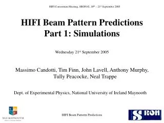
HIFI Consortium Meeting, SRON-G, 18 th – 21 st September 2005. HIFI Beam Pattern Predictions Part 1: Simulations Wednesday 21 st September 2005. Massimo Candotti, Tim Finn, John Lavell, Anthony Murphy, Tully Peacocke, Neal Trappe

E N D
HIFI Consortium Meeting, SRON-G, 18th – 21st September 2005 HIFI Beam Pattern PredictionsPart 1: SimulationsWednesday 21st September 2005 Massimo Candotti, Tim Finn, John Lavell, Anthony Murphy, Tully Peacocke, Neal Trappe Dept. of Experimental Physics, National University of Ireland Maynooth HIFI Beam Patterm Predictions
GRASP model of the HIFI signal path H channels, bands 1 to 6H HIFI Beam Patterm Predictions
Beam pattern prediction:main modelling tools • GRASP • Full physical optics. • Vector fields for both E and H. • Computationally intensive and time consuming, but versatile and accurate. • GLAD • Scalar methods, ray tracing and FFT. • No polarization. • Fast and able to handle the telescope if you ignore strut scattering. • Sources • Mode-matching to predict corrugated horn aperture fields. • PILRAP to give a scalar prediction of the co-polar field at the waist of the lens antennas. HIFI Beam Patterm Predictions
Current state of modelling • GRASP models exist for both polarizations in all bands. • Signal path optics from the mixers to the sky. • LO path optics as far as the LO window. • Telescope modelled to the as-built specification given in the Astrium documentation. Currently no secondary mirror support struts. • GRASP models now include the diplexers. • The roof mirrors are treated as plane mirrors placed at the ridge of the roof to maintain correct path length. Field rotated upon reflection before propagation onwards through the grid. • Telescope model not yet included in the beam propagation. HIFI Beam Patterm Predictions
Continued ……. • In all models the grids are treated as ideal polarizing elements. • Beams on the sky, fields at the focal surface, P1 plane and the LO window have been obtained for Bands 1, 2, 3, 5, 6L and 6H. • GRASP and GLAD models of the calibration unit. • GLAD models exist for most of the system, including the telescope. Used mainly for the higher frequencies. • Can include roof mirrors as ‘black-box’ elements. HIFI Beam Patterm Predictions
Results to be presented • Band 1 • Focal plane field distributions. • On-sky beam patterns: H and V channel pointing offsets. • Coupling to the calibration source. • Band 5 • Problems with lens antenna fields: need to find an equivalent source from measurements of the co-polar fields, calculate the correct mixer mounting position to give an aligned beam. • Band 6H • A few results from Glad models. HIFI Beam Patterm Predictions
Band 1 @ 560GHz • Channel 1H focal plane co-polar field intensity. • Channel 1V focal plane co-polar field intensity. • In both figures the plots are centred on the geometric focus. • Relative pointing offset estimate: 3.7 arc sec. FWHM/9.5 HIFI Beam Patterm Predictions
Band 1 telescope secondary mirror illumination @ 560GHz • Beam quality estimates for the signal path: • Channel 5H: • l/12 P-V • l /30 RMS • Channel 5H: • l /18 P-V • l /42 RMS • Estimated FWHM: • 35.3 arc sec. • Phase map of the co-polar field in telescope stop, channel 5H. HIFI Beam Patterm Predictions
HBB, channel 1H, M6 chop angle 10.4 degrees. Polarization is preserved: X-polar level is –23dB. Co-polar H and V angular separation 89 degrees. CBB, channel 1H, M6 chop angle 8.4 degrees. Shows evidence of beam clipping at SMIR. Cross-polar level –22dB Co-polar H and V angular separation 87 degrees. HBB and CBB illumination @ 560GHz HIFI Beam Patterm Predictions
Band 5: lens antenna fields • Measurements show a displaced and tilted beam from the MSA. • Optical alignment of the three MSA mirrors is too good to account for this: lens antenna beam must be squint. • Use measured data and scanner coordinates to define a source in a GRASP model of the MSA. • Propagate the measured field back to the mixer and derive an apparent source. • Calculate the displacement and tilt of the antenna, correct and propagate the beam back to P1 to check beam alignment. HIFI Beam Patterm Predictions
Band 5 uncorrected beams • Figures show the uncorrected beams at P1: co-polar field for H and V channels at 1193GHz. • The effects of source tilt and displacement are seen in the amplitude and phase plots. • On propagation to the sky the relative beam pointing error is approximately 9.3 arc. sec. (0.53 FWHM) • Estimated beam quality: 5H: l /7.7 P-V, lambda/46 RMS. 5V: l /7.9 P-V, lambda/32 RMS. 17.0 arc sec. FWHM. HIFI Beam Patterm Predictions
Band 5 corrected beams • Figures show the corrected beams at P1: co-polar field for H and V channels at 1193GHz. • The effects of tilting and displacing the source is to bring the beam on axis and remove most of the phase tilt. • On propagation to the sky the relative beam pointing error is approximately 0.2 arc. sec. (0.01 FWHM) • Estimated beam quality: 5H: l /8.1 P-V, lambda/44 RMS. 5V: l /9.3 P-V, lambda/47 RMS. 17.5 arc sec. FWHM. HIFI Beam Patterm Predictions
For band 5 the coupling of the fully corrected and uncorrected beams to a Gaussian in the LO window are: LO coupling predictions • Due to mechanical constraints in the MSA we cannot accommodate complete mixer location correction without re-manufacture. • Will investigate partial correction within the mechanical constraints: preliminary analysis suggests that this will be adequate. HIFI Beam Patterm Predictions
Lens antenna fields • Preliminary measurements lead us to expect the same kinds of problems in bands 6L and 6H that have been seen in band 5. • The same methods: measure – simulate source – correct – will be applied to all lens antenna bands. • Need experimental verification of the validity of the approach: make modified MSA and measure the beams. HIFI Beam Patterm Predictions
Band 6H @ 1818GHz • Source modelled using PILRAP: scalar approximation. • Results that are to be shown were obtained using GLAD. • This is an “ideal” system with faultless lens antenna feed. • Provides a baseline for assessing the quality of the real lens antenna system. HIFI Beam Patterm Predictions
Focal plane field Diffraction limited beams HIFI Beam Patterm Predictions
Gaussicity at the LO window: Channel H: 96.3% Channel V: 96.4% HIFI Beam Patterm Predictions
Work now in progress • Complete simulations of band 5 focal plane fields for comparison with measurements now in progress. • This is in the old, diplexer configuration. • Simulate various feasible corrections to the mixer position. • Measure fields with modified MSA. HIFI Beam Patterm Predictions
Future work • Bands 6L and 6H lens antenna position corrections: • Repeat procedure used in band 5 to get aligned beams. • To include the telescope in the GRASP model and, ultimately, include strut scattering. • Use measured focal plane fields as sources in the GRASP models to predict the beam pattern on the sky. • Derive synthetic calibration data. HIFI Beam Patterm Predictions