Download
1 / 56
560 likes | 604 Views
Explore how GIS mapping software revolutionizes pipeline projects with detailed data collection, joint mapping, and corridor management. Learn about the Oregon Clean Energy Center project overview, key pipeline terminology, and software flexibility. Discover the benefits of Trimble Access Pipelines for surveyors, field crews, and contractors, enhancing efficiency and accuracy in pipeline construction. Join us at the 2016 Ohio GIS Conference to delve deeper into the pipeline industry advancements.

E N D
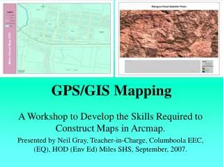
GIS Mapping of Pipelines RJ Lumbrezer, PSSurvey ManagerDGL Consulting Engineers, LLC Ted MunsSales ManagerCity Blueprint of Toledo Hyatt Regency Columbus 2016 Ohio GIS Conference September 28 – 30, 2016 Columbus, Ohio
Agenda • Oregon Clean Energy Center Project Overview • Pipeline Terminology • Why? Then & Now • Software Overview • Data Collection Review • Software Flexibility / Custom Uses • End Results
Oregon Clean Energy CenterProject Overview 23 Miles of Pipeline 27 Sections 172 Parcels 4,500 Welds 63 Directional Bores
The Pipeline Project • Boundary Surveys • Route Planning • Pipe Tally • As-built Survey • Topo Surveys • Corridor Layout • Joint Mapping • Field Tile Locations • Storm Water Run Off • Environmental Studies: Wetlands, Floodplain, Indiana Bat
Pipeline Terminology • (FERC) Federal Energy Regulatory Commission • TALLY is the process of confirming the manufacturer - MANIFEST or MILL DATA • PIPE is commonly known as a JOINT • Joint Mapping is the process of recording the weld and joint data after the pipeline is welded together. • Joint offcut is called a PUP • ROW strictly speaking is legal ROW for pipeline • CORRIDOR is combination of permanent & temporary easement area (area allowed to work within)
Trimble R10 GPS Rover and TSC3 w/ Access Pipelines Trimble TSC3 Trimble R10 GPS Receiver
ODOT VRS (Virtual Reference System) The Ohio Department of Transportation, Office of CADD and Mapping Services operates and maintains a network of 54 strategically located GPS Continuously Operating Reference Stations (CORS) in the State of Ohio Real Time Kinematic surveying Network RTK Horizontal . . . . . . . . 8 mm + 0.5 ppm RMS ~ .03’ + 0.5 ppm Vertical. . . . . . . . . . . 15 mm + 0.5 ppm RMS ~ .06’ + 0.5 ppm
Trimble Access Pipelines Main workflows • Record & validate pipe inventory • Record relationship between joints • Survey welds, bends, etc. after installation, automatically linking all pipe attributes
Trimble Access Pipelines Benefits? • Better data in field & from field • Less processing away from job site • Quicker deliverables to contractors Who benefits? • Surveyors working on pipelines where asset information is required • Field crews & office technicians • Contractors
Trimble Access Pipelines Additional Features • Streamline cover computations • Ensure work within corridor • Record entry & exit to exclusion zones • Slope stationing • Ahead & back stationing • Compute deflection angles • Compute crossing angles & separation
Pipe Alignment Defining Pipe alignment (.rxl) allows: • Compute & record preliminary station & offset when measuring points • Station & offset can be recorded with any measurement • No need to use stakeout to measure points simply to compute station & offset • Station & offset recorded to job as an attribute • Recording as attribute requires Feature & Attribute Library with station & offset fields & configuration to specify which to use • Station & offset values only as accurate as preliminary alignment
Corridor • Pipe alignment combined with corridor left/right width can be used to define working corridor – or inclusion zone – an area you should work within • Complex corridors are better defined by using Shapefile, DXF or LandXML polygon • Warning is displayed a point is stored outside the corridor
Exclusion Zones Supported exclusion zone file types: • Shape files – Polygons • DXF files – Closed polylines • LandXML files – Parcel elements • Warning appears when exclusion zone is entered • Position is recorded when exclusion zone is entered or exited • If point is stored in exclusion zone, a warning will appear asking if it’s appropriate to store in exclusion zone
Data Collection • Completely customizable • Redundancy (both digital & hand written data)
Tally – Getting started • Get manifest from pipe manufacturer • Modify the manifest as necessary to ensure unique ID & remove details not important (if you can’t get a manifest, create a CSV with just a header containing attributes to be collected) • Create or modify Feature code library (FXL) to match manifest/tally headings • Copy Tally CSV & FXL to Controller • Configure Job to link files
Joint Mapping • Primary role of joint mapping is to record details of weld, bend or loose end & joint ahead & joint behind
Joint Mapping – Bends • Like welds, additional bend information can also be configured for storage • Bend type; field or factory • Direction 1; left, right, sag, overbend • Angle 1 • Direction 2 • Angle 2 • You configure the additional information to be stored
Cut Out Welds Tap the cut-out icon then tap Update to remove from the joint map sequence If you cut-out a joint map weld you need to enter a new ID for replacement weld. If you Delete a joint map, you can reuse the ID.
PUPs • The tally typically includes the joint length • As shown in the previous slides, the tally is accessible for review & edit during joint mapping • The tally is easily accessible during the survey of the welds • Any time the joint length is shortened by more than a user-configured distance, you are prompted to create a PUP
PUP Creation The original length was20m It was changed to 17m A dialog appears giving you the option to create a PUP
Automated Cover Computations • Numerous ways to compute cover, simply because different projects/clients/surveyors have different needs • Use solution that works best for you: • From closest natural ground point • From last measured point • From vertical alignment • From surface model
Pipeline / Utility Crossings • Surveying pipeline crossings is another important process most companies perform • The Compute intersection angle function allows to calculate crossing details: • Record angle of intersection • Record separation • Store intersection point • Produce report on crossings
Export & Reporting • All data, including weld & joint ID, joint attributes, cover, crossings calculations etc. are all stored in Trimble Access job • Data flows through to TBC • Reporting in Trimble Access can be used for daily reports • Tally progress • Joint mapping progress • Crossing reports • As-built progress
Deliverables / End Results • Insert .kml file into Google Earth image with data link • Export into Excel spread sheet • Export into a Geodatabase