Download
1 / 26
260 likes | 424 Views
Lasing properties of Arm-Stem type current injection T-shaped quantum wire lasers. ISSP Univ. of Tokyo M2 Makoto Okano. 1. Background and Motivation 2.Structure of current injection QWR 3. Lasing properties of QWR 4.Mechanism of current injection 5.Summary.

E N D
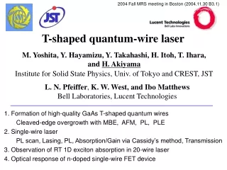
Lasing properties of Arm-Stem typecurrent injection T-shaped quantum wire lasers ISSPUniv. of TokyoM2Makoto Okano 1. Background and Motivation 2.Structure of current injection QWR 3. Lasing properties of QWR 4.Mechanism of current injection 5.Summary
↑Merits:High uniformity & High controllability of structure. ↓Demerit:Difficulty of fabrication. 0.Introduction ~about T-shaped QWR
1.Background and Motivation It is expected that quantum wire laser become better than quantum well laser. ↓ Lasing from current injection T-shaped quantum wire (T-wire) had been reported by W.Wegscheider et al. in 1994.However, there has ever been no concrete detail. ↓ Recently, we developed growth interrupt annealing technique in 2001. This technique makes T-wire high uniformity possible. ↓ We make high uniformity current injection T-wire with the technique, and measure lasing properties of current injection T-wire laser. And then, verify the effects of1D. Advantage: Directly estimate carrier density from current. Easy to measure external quantum efficiency.
2-1.Schemata of two current injection electron through Arm well hole through Arm well Arm-Arm type electron through Arm well hole through stem well Arm-Stem type
2-1.Schemata of two current injection device properties
3. Lasing properties (with HR/HR coating) T=100K Temperature dependence of Ith and ηout EL spectra I-V,I-L curve 100K is the best conditions for Ith and ηout. (effect of transport?) This feature is different than that of Arm-Arm type
I have two questions. • Why do Arm-Stem type performs best at 100K? • 2. Why is threshold ten times as large as arm-arm type’s? • ↓ • So, I have measured un-coated sample in region of low current to develop a thorough understanding of these problems.
4-1. EL spectra with low current (un coated) un-coated EL intensity become strong, but lineshape don’t change.
4-2. Absorption/gain spectra with low current un-coated cf. Optical pumping Current increase gradually, but gain spectra don’t change. Probably, carrier increase imbalance in wire. (Nelectron=Nhole)
4-3. Bias-Voltage depend. of EL Image Ib = 10uA Vb=1.64V Emission from core layer mainly Emission from outside of the cladding layer Ib =2.0mA Vb=4.19V hole accumulation and overflow from core.
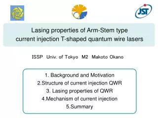
4-4. Carrier confinement and injection Conventional schema Hole overflow in arm well because of weak confinement.
4-4. Carrier confinement and injection Inversion schema Are hole confined because of high barrier of stem well?
5.Summary • We achieved lasing from Arm-Stem type current injection T-wire lasers. But, device properties are not good. And it performs best at 100K. • Injection efficiency is badNew schema may make it well. • Strange temperature dependence Effect of carrier transport? • 2. When current increase gradually, EL intensity increase and gain spectra don’t change. • We assumed because of hole accumulation and hole overflowing. Future prospects 1. Measure the uncoated sample, and check the change in gain spectra. 2. Measure the new schema sample, and compared the old schema.
Fin. Thank you for your kind attention. See you next time…
4-3.温度変化 (HRコートした試料) 各温度で8~10meV程度ピークがレッドシフトする。 ↓ 温度によるBGの変化が表れているとすると 5K→50K 40K→70K 100K→125K 120K→150K 温度上昇で考えるのは妥当か?(QCSE、BGR?)
3-5. 光励起導波路放出光スペクトル at 5K 励起強度に伴って利得が増加 正孔と電子がバランス→利得発生
ゆっくりと利得が発生していく。変化し始めるのは40mW以下。利得がブロード。ゆっくりと利得が発生していく。変化し始めるのは40mW以下。利得がブロード。 利得の変化が比較的大きい。変化し始めるのは同じく40mW以下。 明らかに変化し始めるのが遅い。変化し始めるのは70mW。 光励起によって作られたキャリアが、電流によって注入されたキャリアよりも多くなったときに変化が起こるのか?
Waveguide Emissionの電圧依存性 バイアス電圧が2Vの近傍では、下側包絡線のピーク(P1)は上側包絡線のピーク(P2)よりも高エネルギー側にある。 ドープなし試料と同じ傾向 ELが強くなってくるとその影響で、P1は徐々にP2の低エネルギー側に移動。 過電圧による低エネルギー側の吸収の増加を示唆??
Cassidy法による利得吸収スペクトル導出 α:吸収係数 R :反射率 (Free Spectral Range)
Photo Luminescenceスペクトル at 5K IVは非常にきれいで、低温ではleakしない。 少し均一性は悪いが、高品質な試料が作製できた。
利得吸収スペクトルの電圧依存性 1.2~1.9Vでの利得の変化は、励起強度依存性に近く、徐々に細線にキャリアが注入されていっていると推測される。 しかし、1.9~3.9Vでは明らかに利得が減少していっているのがわかる。 利得の減少がキャリアの減少によるものであれば、上と下の図はほとんど同じになるはずだが、明らかに異なる。 つまり、利得の減少はキャリアの減少ではなく、なんらかの吸収の増加によるものと考えられる。