Download
1 / 16
160 likes | 186 Views
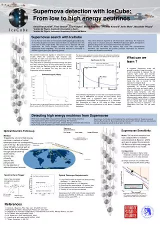
Comprehensive review of IceTop surface component of IceCube array, showcasing scientific goals, cost breakdown, scheduling, station design, tank filling, DOM deployment, and cable layout. Explore calibration, veto functions, and cosmic-ray studies.

E N D
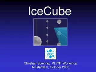
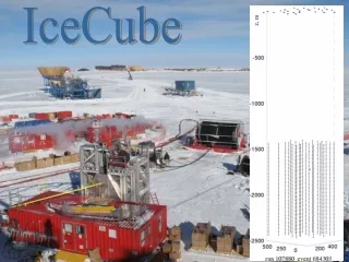
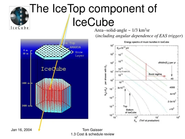
The IceTop component of IceCube Area--solid-angle ~ 1/3 km2sr (including angular dependence of EAS trigger) Tom Gaisser 1.3 Cost & schedule review
Outline • Scientific goals • Pictures of test-tanks & Doms, 03/04 • Cost & schedule review • WBS structure & definitions • Schedule • Budget Tom Gaisser 1.3 Cost & schedule review
IceTop:the surface component of IceCube • A 3-dimensional air shower array for • Veto (i.e. tagging downward events) • Calibration • Primary composition from PeV to EeV • Calibration, composition analyses similar to SPASE-AMANDA but • 5000 x larger acceptance • wider energy range, better resolution • IceTop at high altitude (700 g/cm2) • 125 m spacing between IceTop stations • Ethreshold ~ 300 TeV for > 4 stations in coincidence • Useful rate to EeV Tom Gaisser 1.3 Cost & schedule review
Showers triggering 4 stations give ~300 TeV threshold for EAS array Large showers with E ~ 100-1000 PeV will clarify transition from galactic to extra-galactic cosmic rays. Small showers (2-10 TeV) associated with the dominant m background in the deep detector are detected as 2-tank coincidences at a station. Detection efficiency ~ 5% provides large sample to study this background. Tom Gaisser 1.3 Cost & schedule review
IceTop station schematic • Two Ice Tanks 3.1 m2 x 1 m deep (a la Haverah, Auger) • Coincidence between tanks = potential air shower • Signal in single tank = potential muon • Significant area for horizontal muons • Low Gain/High Gain operation to achieve dynamic range Tank simulation with GEANT-4 Tom Gaisser 1.3 Cost & schedule review
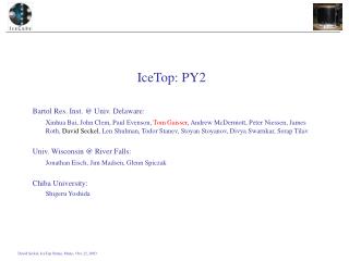
Fill tanks • Tank10 • Successful fill Nov 22 • 20 minutes to fill • < 10 RPSC man hours for transport and filling • Tank09 • Filled Nov 26 Tom Gaisser 1.3 Cost & schedule review
Cable runs looking toward MAPO away from SPASE Tank10 is on the right, Tank09 on the left. Power cable is on the left. There are 5 cables on the right: 2 freeze-control cables, two twisted quads for DOMS, and Stoyan’s cable to read temperatures during the winter. The latter is somewhat thicker than the other four. Tom Gaisser 1.3 Cost & schedule review
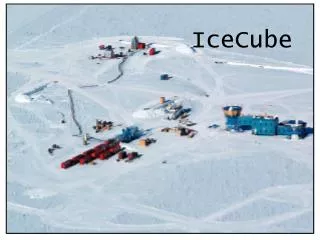
4 IceCube DOMs running From: SMTP%"john.kelley@usap.gov" 15-JAN-2004 15:56:19.45 To: icecube-c@ssec.wisc.edu Subj: First Four IceCube DOMs Deployed I'm pleased to report that the first four IceCube digital optical modules have been successfully deployed at the pole. They are currently frozen into two IceTop surface tanks, located near the SPASE building. The DOMs are operating normally, and we are looking forward to dark-adapting the tanks and taking real data. John Kelley, UW-Madison Tom Gaisser 1.3 Cost & schedule review
WBS structure IceTop is the surface component of IceCube. By detecting cosmic-ray showers in coincidence with the deep detector it provides certain unique calibration and veto functions for neutrino astronomy in addition to permitting IceCube to function as a three-dimensional air shower array for study of cosmic-ray astrophysics up to PeV energies. • 1.3.2 IceTop • 1.3.2.1 Tanks • 1.3.2.2 Cables • 1.3.2.3 DOMs • 1.3.2.4 IceTop specific engineering • 1.3.2.4.1 system design • 1.3.2.4.2 detector simulations • 1.3.2.4.3 Data acquisition • Integration of SPASE • IceTop management Tom Gaisser 1.3 Cost & schedule review
Tanks, DOMs, Cables deployment and Design and build tanks; design and test freezing procedures to provide working ice-Cherenkov detectors for the surface array component of IceCube. Exclusion: Provision of water to fill the tanks is excluded because it will be an integral part of deployment (see 1.2.3.3.4 under 1.2.3.3 Field Season Operations). There is also a need for coordination with drilling (1.2.2) in connection with water supply. Tank deployment is under 1.2. • 1.3.2.1 Tanks • 1.3.2.2 Cables • 1.3.2.3 DOMs Specification of cabling to power and monitor freezing, testing and operation of tanks. Exclusion: Cabling for tank DOMs should be included in the main surface cables (1.3.1.2). We assume the surface cable will include conductors suitable for monitoring the tanks and for providing power during deployment. (1.3.1.2) Connections from the DOMs to the surface cables must be Provided, as well as cables connecting the DOMs to each other.(1.3.1.2) Develop FAT & verification test for IceTop DOMs Integration of optical modules into tanks. Exclusion: Construction of DOMs is excluded because the DOMs for IceTop will be part of DOM production runs (1.3.1.1). Design of modifications that may be needed for IceTop will be carried out in collaboration with 1.3.3 and 1.3.4 as part of IceTop specific engineering (1.3.2.4). Tom Gaisser 1.3 Cost & schedule review
1.3.2.4 IceTop Specific Engineering Design, Maintenance, calibration and operation of the surface component of IceCube to the extent that these require special procedures. IceTop is an integral component of the IceCube detector. To a large extent, both its hardware and software components are similar, if not identical, to those of the deep detector. This element includes integration of air shower detector calibration, DAQ, trigger, reconstruction and simulation into the corresponding IceCube processes. • 1.3.2.4.1 System design Engineering resources • 1.3.2.4.2 Detector simulations • 1.3.2.4.3 Data acquisition add .4.4 and .4.5 Develop engineering resources necessary for the design, verification, calibration and operation of IceTop components. This includes an IceTop instrumentation and development facility and a tank test station on campus at U of Delaware, a tank test station at UW River Falls, mobile test tanks and a tank test station at the SPASE. Develop simulations needed for IceTop design, verification, calibration and operation. Develop air shower simulations of common interest for IceTop and for simulation of backgrounds in the deep detector (in coordination with WBS 1.4.3). e.g. simulation of tank response, simulations for triggering are in this WBS; simulations for background In IceCube are under 1.4.3.1 Design, specify and produce IceTop-specific DAQ firmware and software components, including triggering and feature extraction algorithms in the on-board FPGA and software for data handling, triggering and reconstruction. Specify requirements For IceTop mainboards, including any variations from mainboards to be used in ice. Coordinate with related activities in WBS elements 1.3.4, 1.4 and 1.5. Tom Gaisser 1.3 Cost & schedule review
SPASE • 1.3.2.5 Integration of SPASE • 1.3.2.6 IceTop management Maintenance and operation of the existing SPASE air shower detector to the extent it remains useful as a calibration device for IceCube. Lower threshold subsample of coincidences; tank calibration Local project monitoring and reporting to project office. Tom Gaisser 1.3 Cost & schedule review
Schedule • PY3 PY4 PY5 PY6 PY7 PY8 PY9 • Strings • deployed 4 12 16 18 18 12 • Tanks • deployed 8 24 32 36 36 24 • manufctd 8 24 32 96 • (accel) • Freeze units (*) 8 (+2?) 16 (+2?) 12 0 • manufctd (accel) • Assumes each freeze unit reused up to 5 times. Probably should add • some extras Tom Gaisser 1.3 Cost & schedule review
Hardware costs • Capital • Tanks: 160 @ $6037 = $965,920 • Frz units: 36 @ $6002 = 216,072 • O’flow units 36 @ $ 561 = 20,196 • Sunshade 36 @ $1922 = 69,129 • Misc Tank Equip 38,550 • Test station Equip (inc. $45K at UWRF) 75,000 • 4 test station tanks + ancillary equip 60,000 • Computer cluster 180,000 • Total capital $1,564,867 (+$60K) Tom Gaisser 1.3 Cost & schedule review
Materials & supplies (inc shipping)+ travel (both unburdened) • 1.3.2.1 Tanks $ 18,850 • (not enough for shipping) • 1.3.2.4.1 (Test stations) 31,000 • 1.3.2.4.3 • DAQ computers 27,000 reduce to $15K, move to.4.1 • Misc hardware 100,750 move to .4.1 • 1.3.2.5 -000- • 1.3.2.6 48,000 (replacement work stns) • Total M & S $225,600 • Travel $549,000 Tom Gaisser 1.3 Cost & schedule review
Labor breakdown • By institution person months (total project) • UD: 572, UW: 87, LBNL: 8, UWRF: 7 • Individuals involved part-time Scientists: 13 1 0 1 Engrs, techs: 5 1 2 • Labor cost by Project year (burdened) PY3 4 5 6 7 8 9 10 1.23 1.23 1.14 1.00 0.81 0.70 0.32 0.16 Total: $6.64 M Tom Gaisser 1.3 Cost & schedule review