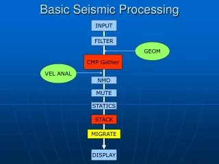
Understanding the Basic Processing Unit: Fetching, Decoding, and Executing Instructions
This lesson focuses on the processing unit, commonly known as the Central Processing Unit (CPU), which is responsible for executing machine-language instructions and coordinating computer activities. We discuss its internal structure and process, including fetching, decoding, and executing instructions. The evolution of processor organization, including pipelined and superscalar operations to enhance performance, is examined. Key concepts such as the program counter (PC), instruction register (IR), and basic operations performed by the processor are also covered to provide a comprehensive understanding of data processing in computing.

Understanding the Basic Processing Unit: Fetching, Decoding, and Executing Instructions
E N D
Presentation Transcript
Basic Processing Unit In this lesson we focus on the processing unit, which executes machine-language instructions and coordinates the activities of other units in a computer. We examine its internal structure and show how it performs the tasks of fetching, decoding, and executing such instructions. The processing unit is often called the central processing unit (CPU). Today’s computers often include several processing units. We will use the term processor in this discussion at the same time. CENG 222 - Spring 2012-2013 Dr. Yuriy ALYEKSYEYENKOV
Basic Processing Unit The organization of processors has evolved over the years, driven by developments in technology and the desire to provide high performance. To achieve high performance, it is prudent to make various functional units of a processor operate in parallel as much as possible. Such processors have a pipelined organization where the execution of an instruction is started before the execution of the preceding instruction is completed. Another approach, known as superscalar operation, is to fetch and start the execution of several instructions at the same time. CENG 222 - Spring 2012-2013 Dr. Yuriy ALYEKSYEYENKOV
Some Fundamental Concepts A typical computing task consists of a series of operations specified by a sequence of machine-language instructions that constitute a program. The processor fetches one instruction at a time and performs the operation specified. Instructions are fetched from successive memory locations until a branch or a jump instruction is encountered. The processor uses the program counter, PC, to keep track of the address of the next instruction to be fetched and executed. After fetching an instruction, the contents of the PC are updated to point to the next instruction in sequence. A branch instruction may cause a different value to be loaded into the PC. When an instruction is fetched, it is placed in the instruction register, IR, from where it is interpreted, or decoded, by the processor’s control circuitry. The IR holds the instruction until its execution is completed. CENG 222 - Spring 2012-2013 Dr. Yuriy ALYEKSYEYENKOV
Some Fundamental Concepts Consider a 32-bit computer in which each instruction is contained in one word in the memory, as in RISC-style instruction set architecture. To execute an instruction, the processor has to perform the following steps: 1. Fetch the contents of the memory location pointed to by the PC. The contents of this location are the instruction to be executed; hence they are loaded into the IR. In register transfer notation, the required action is IR ← [[PC]] 2. Increment the PC to point to the next instruction. Assuming that the memory is byte addressable, the PC is incremented by 4; that is PC ← [PC] + 4 3. Carry out the operation specified by the instruction in the IR. CENG 222 - Spring 2012-2013 Dr. Yuriy ALYEKSYEYENKOV
Some Fundamental Concepts Fetching an instruction and loading it into the IR is usually referred to as the instruction fetch phase. Performing the operation specified in the instruction constitutes the instruction execution phase. With few exceptions, the operation specified by an instruction can be carried out by performing one or more of the following actions: • Read the contents of a given memory location and load them into a processor register. • Read data from one or more processor registers. • Perform an arithmetic or logic operation and place the result into a processor register. • Store data from a processor register into a given memory location. CENG 222 - Spring 2012-2013 Dr. Yuriy ALYEKSYEYENKOV
Some Fundamental Concepts Main hardware components of a processor CENG 222 - Spring 2012-2013 Dr. Yuriy ALYEKSYEYENKOV
Data Processing Hardware A typical computation operates on data stored in registers. These data are processed by combinational circuits, such as adders, and the results are placed into a register. Figure illustrates this structure. A clock signal is used to control the timing of data transfers. The registers comprise edge-triggered flip-flops into which new data are loaded at the active edge of the clock. Here, we assume that the rising edge of the clock is the active edge. The clock period, which is the time between two successive rising edges, must be long enough to allow the combinational circuit to produce the correct result. CENG 222 - Spring 2012-2013 Dr. Yuriy ALYEKSYEYENKOV
Data Processing Hardware Basic structure for data processing. CENG 222 - Spring 2012-2013 Dr. Yuriy ALYEKSYEYENKOV
Data Processing Hardware A hardware structure with multiple stages. CENG 222 - Spring 2012-2013 Dr. Yuriy ALYEKSYEYENKOV
Instruction Execution Load Instructions Consider the instruction Load R5, X(R7) which uses the Index addressing mode to load a word of data from memory location X + [R7] into register R5. Execution of this instruction involves the following actions: • Fetch the instruction from the memory. • Increment the program counter. • Decode the instruction to determine the operation to be performed. • Read register R7. • Add the immediate value X to the contents of R7. • Use the sum X + [R7] as the effective address of the source operand, and read the contents of that location in the memory. • Load the data received from the memory into the destination register, R5. CENG 222 - Spring 2012-2013 Dr. Yuriy ALYEKSYEYENKOV
Instruction Execution Load Instructions Depending on how the hardware is organized, some of these actions can be performed at the same time. In the discussion that follows, we will assume that the processor has five hardware stages, which is a commonly used arrangement in RISC-style processors. Execution of each instruction is divided into five steps, such that each step is carried out by one hardware stage. In this case, fetching and executing the Load instruction above can be completed as follows: 1. Fetch the instruction and increment the program counter. 2. Decode the instruction and read the contents of register R7 in the register file. 3. Compute the effective address. 4. Read the memory source operand. 5. Load the operand into the destination register, R5. CENG 222 - Spring 2012-2013 Dr. Yuriy ALYEKSYEYENKOV
Instruction Execution Arithmetic and Logic Instructions Instructions that involve an arithmetic or logic operation can be executed using similar steps. They differ from the Load instruction in two ways: • There are either two source registers, or a source register and an immediate source operand. • No access to memory operands is required. A typical instruction of this type is Add R3, R4, R5 It requires the following steps: 1. Fetch the instruction and increment the program counter. 2. Decode the instruction and read the contents of source registers R4 and R5. 3. Compute the sum [R4] + [R5]. 4. Load the result into the destination register, R3. Instruction should be extended to five steps, patterned along the steps of the Loadinstruction. We can insert anempty step: No action. CENG 222 - Spring 2012-2013 Dr. Yuriy ALYEKSYEYENKOV
Instruction Execution Arithmetic and Logic Instructions If the instruction uses an immediate operand, as in Add R3, R4, #1000 the immediate value is given in the instruction word. Once the instruction is loaded into the IR, the immediate value is available for use in the addition operation. The same sequence can be used, with steps 2 and 3 modified as: 2. Decode the instruction and read register R4. 3. Compute the sum [R4] + 1000. Here again we add an empty step: No action to have 5 steps totally. CENG 222 - Spring 2012-2013 Dr. Yuriy ALYEKSYEYENKOV
Instruction Execution Store Instructions For example, the instruction Store R6, X(R8) stores the contents of register R6 into memory location X + [R8]. It can be implemented as follows: 1. Fetch the instruction and increment the program counter. 2. Decode the instruction and read registers R6 and R8. 3. Compute the effective address X + [R8]. 4. Store the contents of register R6 into memory location X + [R8]. 5. No action. CENG 222 - Spring 2012-2013 Dr. Yuriy ALYEKSYEYENKOV
Hardware Components Register File General-purpose registers are usually implemented in the form of a register file, which is a small and fast memory block. It consists of an array of storage elements, with access circuitry that enables data to be read from or written into any register. The access circuitry is designed to enable two registers to be read at the same time, making their contents available at two separate outputs, A and B. The register file has two address inputs that select the two registers to be read. These inputs are connected to the fields in the IR that specify the source registers, so that the required registers can be read. The register file also has a data input, C, and a corresponding address input to select the register into which data are to be written. This address input is connected to the IR field that specifies the destination register of the instruction. CENG 222 - Spring 2012-2013 Dr. Yuriy ALYEKSYEYENKOV
Hardware Components Register File Two alternatives for implementing a dual-ported register file. CENG 222 - Spring 2012-2013 Dr. Yuriy ALYEKSYEYENKOV
Hardware Components ALU The arithmetic and logic unit is used to manipulate data. It performs arithmetic operations such as addition and subtraction, and logic operations such as AND, OR, and XOR. Conceptually, the register file and the ALU may be connected as shown in Figure. When an instruction that performs an arithmetic or logic operation is being executed, the contents of the two registers specified in the instruction are read from the register file and become available at outputs A and B. Output A is connected directly to the first input of the ALU, InA, and output B is connected to a multiplexer, MuxB. The multiplexer selects either output Bof the register file or the immediate value in the IR to be connected to the second ALUinput, InB. The output of the ALU is connected to the data input, C, of the register file so that the results of a computation can be loaded into the destination register. CENG 222 - Spring 2012-2013 Dr. Yuriy ALYEKSYEYENKOV
Hardware Components ALU Conceptual view of the hardware needed for computation CENG 222 - Spring 2012-2013 Dr. Yuriy ALYEKSYEYENKOV
Hardware Components Datapath Instruction processing consists of two phases: the fetch phase and the execution phase. It is convenient to divide the processor hardware into two corresponding sections. One section fetches instructions and the other executes them. The section that fetches instructions is also responsible for decoding them and for generating the control signals that cause appropriate actions to take place in the execution section. The execution section reads the data operands specified in an instruction, performs the required computations, and stores the results. We now need to organize the hardware into a multi-stage structure similar to that introduced before, with stages corresponding to the five steps. The actions taken in each of the five stages are completed in one clock cycle. This hardware is often referred to as the datapath. CENG 222 - Spring 2012-2013 Dr. Yuriy ALYEKSYEYENKOV
Hardware Components Datapath It is necessary to insert registers between stages. Inter-stage registers hold the results produced in one stage so that they can be used as inputs to the next stage during the next clock cycle. CENG 222 - Spring 2012-2013 Dr. Yuriy ALYEKSYEYENKOV
Hardware Components Datapath CENG 222 - Spring 2012-2013 Dr. Yuriy ALYEKSYEYENKOV
Hardware Components Instruction Fetch Section The addresses used to access the memory come from the PC when fetching instructions and from register RZ in the datapath when accessing instruction operands. Multiplexer MuxMA selects one of these two sources to be sent to the processor-memory interface. The PCis included in a larger block, the instruction address generator, which updates the contents of the PC after each instruction is fetched. The instruction read from the memory is loaded into the IR, where it stays until its execution is completed and the next instruction is fetched. The contents of the IR are examined by the control circuitry to generate the signals needed to control all the processor’s hardware. They are also used by the block labeled Immediate. CENG 222 - Spring 2012-2013 Dr. Yuriy ALYEKSYEYENKOV
Hardware Components Instruction Fetch Section Instruction fetch section CENG 222 - Spring 2012-2013 Dr. Yuriy ALYEKSYEYENKOV
Hardware Components Instruction Fetch Section Instruction address generator. CENG 222 - Spring 2012-2013 Dr. Yuriy ALYEKSYEYENKOV
Hardware Components Instruction Fetch and Execution Steps Consider again the instruction Add R3, R4, R5 The steps for fetching and executing this instruction are given in figure. CENG 222 - Spring 2012-2013 Dr. Yuriy ALYEKSYEYENKOV
Hardware Components Instruction Fetch and Execution Steps Instruction encoding. CENG 222 - Spring 2012-2013 Dr. Yuriy ALYEKSYEYENKOV
Instruction Fetch and Execution Steps Assume that the instruction is encoded using the format shown. After the instruction has been fetched from the memory and placed in the IR, the source register addresses are available in fields IR31−27 and IR26−22. These two fields are connected to the address inputs for ports A and B of the register file. As a result, registers R4and R5 are read and their contents placed in registers RA and RB, respectively, at the end of step 2. In the next step, the control circuitry sets MuxB to select input 0, thus connecting register RB to input InBof the ALU. At the same time, it causes the ALU to perform an addition operation. Since register RA is connected to input InA, the ALU produces the required sum [RA] + [RB], which is loaded into register RZ at the end of step 3. In step 4, multiplexer MuxYselects input 0, thus causing the contents of RZ to be transferred to RY. The control circuitry connects the destination address field of the Add instruction, IR21−17, to the address input for port C of the register file. In step 5, it issues a Writecommand to the register file, causing the contents of register RY to be written into register R3. Hardware Components CENG 222 - Spring 2012-2013 Dr. Yuriy ALYEKSYEYENKOV
Branching Instructions are fetched from sequential word locations in the memory during straight-line program execution. Whenever an instruction is fetched, the processor increments the PCby 4to point to the next word. This execution pattern continues until a branch or subroutine call instruction loads a new address into the PC. Subroutine call instructions also save the return address, to be used when returning to the calling program. In this section we examine the actions needed to implement these instructions. Interrupts from I/O devices and software interrupt instructions are handled in a similar manner. Branch instructions specify the branch target address relative to the PC. A branch offset given as an immediate value in the instruction is added to the current contents of the PC. The number of bits used for this offset is considerably less than the word length of the computer, because space is needed within the instruction to specify the OP code and the branch condition. Hence, the range of addresses that can be reached by a branch instruction is limited. Hardware Components CENG 222 - Spring 2012-2013 Dr. Yuriy ALYEKSYEYENKOV
Branch Instructions Hardware Components Sequence of actions needed to fetch and execute an unconditional branch instruction. Sequence of actions needed to fetch and execute the instruction: Branch_if_[R5]=[R6] LOOP. CENG 222 - Spring 2012-2013 Dr. Yuriy ALYEKSYEYENKOV
Hardware Components Subroutine Call Instructions Sequence of actions needed to fetch and execute the instruction: Call_Register R9. Address of the first instruction of the subroutine is in R9. The return address of the subroutine, which is the previous contents of the PC, is to be saved in a general-purpose register called LINK in the register file. CENG 222 - Spring 2012-2013 Dr. Yuriy ALYEKSYEYENKOV
Hardware Components Waiting for Memory The role of the processor-memory interface circuit is to control data transfers between the processor and the memory. Modern processors use fast, on-chip cache memories. Most of the time, the instruction or data referenced in memory Read and Write operations are found in the cache, in which case the operation is completed in one clock cycle. When the requested information is not in the cache and has to be fetched from the main memory, several clock cycles may be needed. The interface circuit must inform the processor’s control circuitry about such situations, to delay subsequent execution steps until the memory operation is completed. CENG 222 - Spring 2012-2013 Dr. Yuriy ALYEKSYEYENKOV
Hardware Components Waiting for Memory Assume that the processor-memory interface circuit generates a signal called Memory Function Completed (MFC). It asserts this signal when a requested memory Reador Write operation has been completed. The processor’s control circuitry checks this signal during any processing step in which it issues a memory Reador Writerequest, to determine when it can proceed to the next step. When the requested data are found in the cache, the interface circuit asserts the MFC signal before the end of the same clock cycle in which the memory request is issued. Hence, instruction execution continues uninterrupted. If access to the main memory is required, the interface circuit delays asserting MFC until the operation is completed. In this case, the processor’s control circuitry must extend the duration of the execution step for as many clock cycles as needed, until MFC is asserted. We will use the command Wait for MFC to indicate that a given execution step must be extended, if necessary, until a memory operation is completed. When MFC is received, the actions specified in the step are completed, and the processor proceeds to the next step in the execution sequence. CENG 222 - Spring 2012-2013 Dr. Yuriy ALYEKSYEYENKOV
Hardware Components Control Signals The operation of the processor’s hardware components is governed by control signals. These signals determine which multiplexer input is selected, what operation is performed by the ALU, and so on. In this section we discuss the signals needed to control the operation of the components in processor. It is instructive to begin by recalling how data flow through the four stages of the datapath. In each clock cycle, the results of the actions that take place in one stage are stored in inter-stage registers, to be available for use by the next stage in the next clock cycle. Since data are transferred from one stage to the next in every clock cycle, inter-stage registers are always enabled. This is the case for registers RA, RB, RZ, RY, RM, and PC-Temp. The contents of the other registers, namely, the PC, the IR, and the register file, must not be changed in every clock cycle. New data are loaded into these registers only when called for in a particular processing step. They must be enabled only at those times. CENG 222 - Spring 2012-2013 Dr. Yuriy ALYEKSYEYENKOV
Hardware Components Control Signals Control signals for the instruction address generator CENG 222 - Spring 2012-2013 Dr. Yuriy ALYEKSYEYENKOV
Hardware Components Control Signals page 175 Processor-memory interface and IR control signals CENG 222 - Spring 2012-2013 Dr. Yuriy ALYEKSYEYENKOV
Control Unıt CENG 222 - Spring 2012-2013 Dr. Yuriy ALYEKSYEYENKOV
Hardwired Control Previous sections described the actions needed to fetch and execute instructions. We nowexamine how the processor generates the control signals that cause these actions to take place in the correct sequence and at the right time. There are two basic approaches: hardwiredcontrol and microprogrammed control. An instruction is executed in a sequence of steps, where each step requires one clockcycle. Hence, a step counter may be used to keep track of the progress of execution. CENG 222 - Spring 2012-2013 Dr. Yuriy ALYEKSYEYENKOV
Hardwired Control Several actions are performed in each step, depending on the instruction being executed. In some cases, such as for branch instructions, the actions taken depend on tests applied to the result of a computation or a comparison operation. External signals, such as interrupt requests, may also influence the actions to be performed. Thus, the setting of the control signals depends on: • Contents of the step counter • Contents of the instruction register • The result of a computation or a comparison operation • External input signals, such as interrupt requests CENG 222 - Spring 2012-2013 Dr. Yuriy ALYEKSYEYENKOV
Hardwired Control Generation of the control signals. CENG 222 - Spring 2012-2013 Dr. Yuriy ALYEKSYEYENKOV
Hardwired Control The instruction decoder interprets the OP-code and addressing mode informationin the IR and sets to 1 the corresponding INSi output. During each clock cycle, one ofthe outputs T1 to T5 of the step counter is set to 1 to indicate which of the five steps involvedin fetching and executing instructions is being carried out. Since all instructions arecompleted in five steps, a modulo-5 counter may be used. The control signal generator isa combinational circuit that produces the necessary control signals based on all its inputs.The required settings of the control signals can be determined from the action sequencesthat implement each of the instructions represented by the signals INS1 to INSm. CENG 222 - Spring 2012-2013 Dr. Yuriy ALYEKSYEYENKOV
Hardwired Control Datapath Control Signals Instructions that handle data include Load, Store, and all computational instructions. Theyperform various data movement and manipulation operations using the processor’s datapath,whose control signals were shown in figures. Once an instruction is loadedinto the IR, the instruction decoder interprets its contents to determine the actions needed.At the same time, the source registers are read and their contents become available at theAand B outputs of the register file. As mentioned earlier, inter-stage registers RA, RB,RZ, RM, and RY are always enabled. This means that data flow automatically from onedatapath stage to the next on every active edge of the clock signal. CENG 222 - Spring 2012-2013 Dr. Yuriy ALYEKSYEYENKOV
Hardwired Control Datapath Control Signals The desired setting of various control signals can be determined by examining the actions taken in each execution step of every instruction. For example, the RF_writesignal is set to 1 in step T5 during execution of an instruction that writes data into the register file. It may be generated by the logic expression RF_write = T5 · (ALU + Load + Call) where ALU stands for all instructions that perform arithmetic or logic operations, Load stands for all Load instructions, and Call stands for all subroutine-call and software-interrupt instructions. The RF_write signal is a function of both the instruction and the timing signals. CENG 222 - Spring 2012-2013 Dr. Yuriy ALYEKSYEYENKOV
Microprogrammed Control Control signals are generated for each execution step based on the instruction in the IR. In hardwired control, these signals are generated by circuits that interpret the contents of the IR as well as the timing signals derived from a step counter. Instead of employing such circuits, it is possible to use a “software" approach, in which the desired setting of the control signals in each step is determined by a program stored in a special memory. The control program is called a microprogram to distinguish it from the program being executed by the processor. The microprogram is stored on the processor chip in a small and fast memory called the microprogram memory or the control store. Suppose that n control signals are needed. Let each control signal be represented by a bit in an n-bit word, which is often referred to as a control word or a microinstruction. Each bit in that word specifies the setting of the corresponding signal for a particular step in the execution flow. One control word is stored in the microprogram memory for each step in the execution sequence of an instruction. CENG 222 - Spring 2012-2013 Dr. Yuriy ALYEKSYEYENKOV
Microprogrammed Control CENG 222 - Spring 2012-2013 Dr. Yuriy ALYEKSYEYENKOV
Microprogrammed Control CENG 222 - Spring 2012-2013 Dr. Yuriy ALYEKSYEYENKOV