Basic Processing Unit Operations
This resource covers the implementation of computers, focusing on data representation, conversion, and operation instruction representation. It includes lectures on von Neumann architecture, digital logic, memory organization, and finite state machines. The Processing Unit's basic processing cycle, types of operations, and control mechanisms are explained in detail. Various topics such as register transfer, memory fetching, storing, arithmetic/logic operations, branching, and complete instruction execution are covered.

Basic Processing Unit Operations
E N D
Presentation Transcript
Basic Processing Unit(Chapter 7) http://www.pds.ewi.tudelft.nl/~iosup/Courses/2011_ti1400_7.ppt
Problem: How to Implement Computers? Computers Data representation, conversion, and op.Instruction repr. and use Lectures 3,4,5,6 Programmable Devices Memory organizationProgram sequencingvon Neumann archi.Instruction levels Lecture 2 Digital logicMemory elementsOther building blocks (Multiplexer,Decoder)Finite State Machines Circuit Design Lecture 1 Why Computer Organization Matters? History of Computing(1642-2011) Lecture 0
Problem instruction ? y Decoder f ALU a y Reg
X: 1 Y: 2 Z: 3 • • READ(X) READ(Y) ADD(X,Y,Z) WRITE(Z) Lecture 2Von Neumann Architecture Memory (Central) Processing Unit TEMP_A: TEMP_B: RESULT: arithmetic unit Input IR: CONTROL Output PC:
The Processing Unit Basic Processing Cycle Types of Operations Control Mechanisms 5
Basic Processing Cycle • Assume an instruction occupies a 32 bit single word in byte addressable memory • Basic cycleto be implemented: 1. Fetch instruction pointed to by PC and put it into the Instruction Register (IR): [IR] M([PC]) 2. Increment PC:[PC] [PC] + 4 3. Perform actions as specified in IR
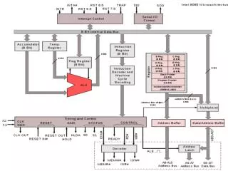
Organization CPU bus Decoder PC control MAR IR memory bus MDR Register file R0 Y R1 R2 ALU Rn-1 Z
MUX Register gating CPU bus Y_in Const 4 Ri_in x Y x Ri Select x ALU Z_in x Ri_out Z x Z_out
R/W R/W R/W C C C D D D Q Q Q Edge-triggered D flip-flop Register gating Multiplexer R1_in R2_in R3_in 1 0 I I I C C C R1_out R2_out R3_out 1 bit of common bus line Tri-state gate: high impedance iff Ri_out=0, Q iff Ri_out=1
Multiple Datapaths Bus A R0 Y R1 R2 R3 ALU register file Bus B Bus C
The Processing Unit Basic Processing Cycle Types of Operations Control Mechanisms • Register Transfer • Fetch from Memory • Store to Memory • Arithmetic/Logic Ops. • Complete Example • Branching Ops. 11
2. Types of Operations • Operation cycle includes: • Transfer datafrom register to register or to ALU • Fetchcontents of memory location and put in one of the CPU registers • Storecontents of CPU register in memory location • Perform arithmetic or logic operation
2.1. Register Transfers R_out CPU bus Copy contents of R1 to R3 1.Address_out=R1 2. R_out 3. Address_in=R3 4. R_in R0 Y R1 R2 ALU R3 Z register file 1. R1_out 2. R3_in Address_out R_in Address_in
2.2. Fetch from Memory (1) Memory bus Data lines Internal processor bus MDR_outE MDR_out x x MDR x x MDR_in MDR_inE
2.2. Fetch from memory (2) e.g., Move (Ri),Rj Control Step 1 1. MAR [Ri] 2. Start read on memory bus 3. Wait for MFC response 4. Load MDR from memory bus 5. Rj [MDR] Memory Function Complete Control Step 2 Control Step 3 Address MAR Data MDR CPU Read Memory MFC
Signal Activation Sequence Fetch from memory (3) Internal processor bus Control Step 1. Ri_out, MAR_in, Read Control Step 2. MDR_inE, WMFC Control Step 3. MDR_out, Rj_in Ri_in x MDR_outE MDR_out Ri x x Memory bus Data lines MDR x x x Ri_out MDR_in MDR_inE
2.2. Fetch from Memory (4) Timing of the Operation 1 2 3 CLK 1. Ri_out, MAR_in, Read 2. MDR_inE, WMFC 3. MDR_out, Rj_in MAR_in address MAR to Mem.Bus New Address Read MR Mem.Read Cmd. MDR_inE Data Mem.Bus to MDR Value MFC Mem.Fnc.Complete MDR_out
2.3. Store to Memory e.g., Move Rj,(Ri) 1. Ri_out, MAR_in 2. Rj_out, MDR_in, Write 3. MDR_outE, WMFC Address Data Memory CPU Write MFC
2.4. Arithmetic Operation ADD R3,R2,R1 Step Action 1. Address_out R1 Y_in R_out 2. Address_out R2 R_out F_alu “ADD” Z_in Address_in R3 Z_out R_in
1. Address_out R1 Y_in R_out Register Transfers R_out CPU bus R0 Y_in Y R1 R2 ALU R3 Z register file Address_out
Arithmetic Operation ADD R3,R2,R1 Step Action 1. Address_out R1 Y_in R_out 2. Address_out R2 R_out F_alu “ADD” Z_in Address_in R3 Z_out R_in
2. Address_out R2 R_out F_alu “ADD” Z_in Register Transfers CPU bus R_out R0 Y_in Y R1 R2 F_alu ALU R3 Z_in Z register file Address_out
Arithmetic Operation ADD R3,R2,R1 Step Action 1. Address_out R1 Y_in R_out 2. Address_out R2 R_out F_alu “ADD” Z_in Address_in R3 Z_out R_in
Address_in R3 Z_out R_in Register Transfers CPU bus R0 Y R1 R2 ALU R3 Z register file R_in Z_out Address_in
Steps in time CPU bus Step 1 2 3 Y_in Y Y_in ALU Z_in Z_in Z Z_out R_in Z_out
The Processing Unit Basic Processing Cycle Types of Operations Control Mechanisms • Register Transfer • Fetch from Memory • Store to Memory • Arithmetic/Logic Ops. • Complete Example • Branching Ops. 27
2.5. Execution of a Complete Instruction 1. Fetch instruction 2. Fetch the operand 3. Perform operation 4. Store result • Example ADD (R3),R1 [R1] M([R3]) + [R1]
Execution fetch (1) Step 1-3: Instruction fetch and PC update Step Action 1 PC_out, MAR_in, Read Set carry-in ALU F_alu = “ADD” Z_in Z_out, PC_in Wait for MFC 3 MDR_out, IR_in [PC][PC ]+1 [IR]M([PC ]) Note: for architectures having PC:=PC+4 a different scheme must be used
1. PC_out, MAR_in, Read Set carry-in ALU F_alu = “ADD” Z_in Fetch instruction Q Why MAR_in? MAR_in MAR PC_out IR PC ADD ALU MDR carry Z_in Z Read WFMC Q Why Set carry-in ALU?
Execution fetch (2) Step 1-3: instruction fetch and PC update Step Action 1 PC_out, MAR_in, Read Set carry-in ALU F_alu = “ADD” Z_in Z_out, PC_in Wait for MFC 3 MDR_out, IR_in [PC][PC ]+1 [IR]M([PC ])
. Z_out, PC_in Wait for MFC Fetch instruction MAR_in MAR PC_in IR PC ALU MDR MDR_in Z Read Z_out Q What is read into MDR? WFMC
Execution fetch (3) Step 1-3: instruction fetch and PC update Step Action 1 PC_out, MAR_in, Read Set carry-in ALU F_alu = “ADD” Z_in Z_out, PC_in Wait for MFC 3 MDR_out, IR_in [PC ] [PC ]+1 [IR] M([PC ])
3. MDR_out, IR_in Fetch instruction Q What is loaded into IR? MAR IR PC IR_in ALU MDR Z Read MDR_out WFMC
Execute Step Action 4 Address_out=R3, R_out MAR_in Read Address_out=R1, R_out Y_in, Wait for MFC 6 MDR_out, Z_in F_alu = “ADD” 7 Address_in=R1, R_in Z_out, End Step 4 and 5: operand fetch Perform addition Store Result
Q Role of Decoder? 4. R3_out MAR_in Read Execute CPU bus Read PC Decoder control MAR IR memory bus MDR register file R0 Y R1 R2 ALU R3 Z
Execute Step Action 4 Address_out=R3, R_out MAR_in Read Address_out=R1, R_out Y_in, Wait for MFC 6 MDR_out, Z_in F_alu = “ADD” 7 Address_in=R1, R_in Z_out, End Step 4 and 5: operand fetch Perform addition Store Result
Q Where does MDRread from? . R1_out Y_in, Wait for MFC Execute CPU bus Decoder WFMC PC control MAR IR memory bus MDR R0 Y R1 R2 ALU R3 Z register file
Execute Step Action 4 Address_out=R3, R_out MAR_in Read Address_out=R1, R_out Y_in, Wait for MFC 6 MDR_out, Z_in F_alu = “ADD” 7 Address_in=R1, R_in Z_out, End Step 4 and 5: operand fetch Perform addition Store Result
Q Who sets F_alu to ADD? 6. MDR_out, Z_in F_alu = “ADD” Execute CPU bus Decoder PC control MAR IR memory bus MDR register file R0 Y R1 R2 ALU Q Why Z_in? R3 Z
Execute Step Action 4 Address_out=R3, R_out MAR_in Read Address_out=R1, R_out Y_in, Wait for MFC 6 MDR_out, Z_in F_alu = “ADD” 7 Address_in=R1, R_in Z_out, End Step 4 and 5: operand fetch Perform addition Store Result
Q Role of End? 7. R1_in Z_out, End Execute CPU bus Decoder PC control MAR IR memory bus MDR register file R0 Y R1 R2 ALU R3 Z
The Processing Unit Basic Processing Cycle Types of Operations Control Mechanisms • Register Transfer • Fetch from Memory • Store to Memory • Arithmetic/Logic Ops. • Complete Example • Branching Ops. 43
2.6. Branching Jump PC+Offset Step Action 1-3 <instruction fetch as in previous example> PC_out, Y_in 5 Offset-field-IR_out F_alu = “ADD” Z_in 6 PC_in Z_out, End
. PC_out, Y_in Branching CPU bus Decoder PC control MAR IR memory bus MDR register file R0 Y R1 R2 ALU R3 Z
Branching Step Action 1-3 <instruction fetch as in previous example> PC_out, Y_in 5 Offset-field-IR_out F_alu = “ADD” Z_in 6 PC_in Z_out, End
5. Offset-field-IR_out F_alu = “ADD” Z_in Branching CPU bus Decoder PC control MAR IR memory bus MDR register file R0 Y R1 R2 ALU R3 Z
Branching Step Action 1-3 <instruction fetch as in previous example> PC_out, Y_in 5 Offset-field-IR_out F_alu = “ADD” Z_in 6 PC_in Z_out, End
6. PC_in Z_out, End Branching CPU bus Decoder PC control MAR IR memory bus MDR R0 Y R1 R2 ALU R3 Z register file
Conditional branching JN PC+Offset Step Action 1-3 <instruction fetch as in previous example> PC_out, Y_in If N=0 then End 5 Offset-field-IR_out F_alu = “ADD” Z_in 6 PC_in Z_out, End If not Negative
The Processing Unit Basic Processing Cycle Types of Operations Control Mechanisms • Hardwired • Micro-Programmed Q Who sets F_alu to ADD? 51