Exploring ELIC: Advancements in Electron-Ion Collider Design at JLab
The workshop at the University of Washington on September 13, 2010, provided insights into the Electron-Ion Collider (ELIC) development at JLab. Key discussions included the design status, critical R&D pathways, and high luminosity goals (up to 10^35 cm^-2 s^-1) to support future nuclear science programs. The evolving design of a Medium-energy Electron-Ion Collider (MEIC) was highlighted, emphasizing enhanced luminosity, high polarization (>80%), and comprehensive machine design optimizations aimed at improving scientific productivity in particle physics.

Exploring ELIC: Advancements in Electron-Ion Collider Design at JLab
E N D
Presentation Transcript
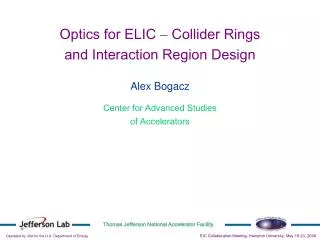
ELIC Accelerator Design Balša Terzić CASA For the JLab EIC Study Group Workshop on Perturbative and Non-perturbative Aspects of QCD at Collider Energies University of Washington, September 13, 2010
Outline • Introduction and the big picture • Machine design status • Critical R&D and path forward • Summary
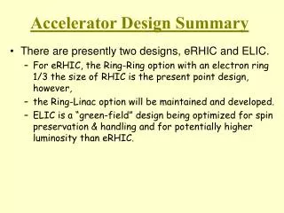
ELIC: JLab’s Future Nuclear Science Program Over the last decade: • JLab has been developing a preliminary design of an electron-ion collider (ELIC) based on the CEBAF recirculating SRF linac • Requirements of the future nuclear science program drives ELIC design efforts to focus on achieving: • ultra-high luminosity per detector (up to 1035cm-2s-1) in multiple detectors • high polarization (>80%) for both electrons & light ions Over the last 12 months: • We have made significant progress on design optimization • The primary focus is on a Medium-energy Electron Ion Collider ( ) as the best compromise between science, technology and project cost • Energy range is up to 100 GeV ions and 11 GeV electrons • A well-defined upgrade capability to higher energies is maintained (ELIC) • High luminosity & high polarization continue to be the design drivers
Highlights of Last Six Months of MEIC Design Activities • Continuing design optimization • Tuning main machine parameters to serve better the science program • Now aim for high luminosity AND full detector acceptance • Simplified design and reduced R&D requirements • Focused on detailed design of major components • Completed baseline design of two collider rings • Completed 1st design of Figure-8 pre-booster • Completed beam polarization scheme with universal electron spin rotators • Updated IR optics design • Continued work on critical R&D • Beam-beam simulations • Nonlinear beam dynamics and instabilities • Chromatic corrections
Short-Term Strategy: 6-Month Design “Contract” • MEIC accelerator team is committed to completing a MEIC designaccording to recommendations by the International Advisory Comm. • Focus of MEIC accelerator team during the “contract” period is to work out a complete machine design with sufficient technical detail • Design “contract” will be reviewed every 6 months and the designspecifications updated to reflect developments in: • Nuclear science program • Accelerator R&D • We are taking a conservative technical position by limiting many MEIC design parameters within or close to the present state of the art in order to minimize technical uncertainty • Maximum peak field of ion superconducting dipole is 6 T • Maximum synchrotron radiation power density is 20 kW/m • Maximum betatron value at final focusing quad is 2.5 km (field gradient <200 T/m)
Short-Term Strategy: 6-Month Design “Contract” This conservative technical design will form a baseline for future design optimization guided by: Evolution of the science program Technology innovation and R&D advances Our present design (assuming 6T magnets) has the following features: CM energy up to 51 GeV: up to 11 GeV electron, 60 (30) GeV proton (ion) Upgrade option to high energy 3 IPs, at least 2 of which are available for medium energy collisions Luminosity up to of order 1034 cm-2s-1per collision point Full acceptance for at least one medium-energy detector(large acceptance for other detectors) High polarization for both electron and light ion beams
Outline Introduction and the big picture Machine design status Critical R&D and path forward Summary
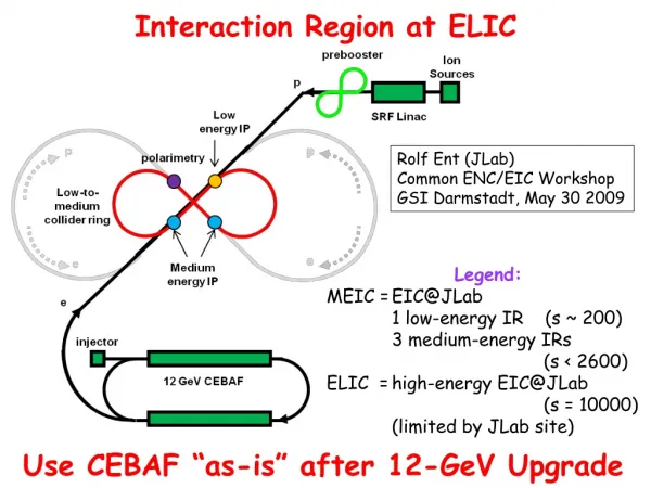
MEIC : Medium Energy EIC medium-energy IPs polarimetry low-energy IP • Three compact rings: • 3 to 11 GeV electron • Up to 12 GeV/c proton (warm) • Up to 60 GeV/c proton (cold)
MEIC : Detailed Layout warm ring cold ring
ELIC: High Energy & Staging Straight section Serves as a large booster to the full energy collider ring Arc
MEIC Ring-Ring Design Features Ultra-high luminosity Polarized electrons and polarized light ions (longitudinal and transverse at IP) Up to 3 IPs (detectors) for high science productivity “Figure-8” ion and lepton storage rings Ensures spin preservation and ease of spin manipulation Avoids energy-dependent spin sensitivity for all species Only practical way to accommodate polarized deuterons 12 GeV CEBAF meets MEIC requirements Simultaneous operation of collider & CEBAF fixed target program possible Experiments with polarized positron beam would be possible
MEIC Luminosity: 1 km Ring, 8 Tesla Assuming maximum peak field for ion magnets of 8 Tesla, highest proton energy can be 96 GeV Full acceptance High luminosity
The second option is using 1 km medium-energy ion ring for higher proton beam current at 30 GeV protons for lowering the space charge tune-shift ELIC Luminosity: 2.5 km Ring, 8 Tesla Full acceptance High luminosity
MEIC & ELIC: Luminosity Vs. CM Energy e + p facilities e + A facilities https://eic.jlab.org/wiki/index.php/Machine_designs
MEIC Adopts Proven Luminosity Approaches High luminosity at B factories comes from: Very small β* (~6 mm) to reach very small spot sizes at collision points Very short bunch length (σz~ β*) to avoid hour-glass effect Very small bunch charge which makes very short bunch possible High bunch repetition rate restores high average current and luminosity Synchrotron radiation damping KEK-B and PEPII already over21034cm-2 s-1 JLab believes these ideas should be replicated in the next electron-ion collider ( ): high-luminosity detector
Figure-8 Ion Rings • Figure-8 is optimum for polarized ion beams • Simple solution to preserve full ion polarization by avoiding spin resonances during acceleration • Energy independence of spin tune • g-2 is small for deuterons; a figure-8 ring is the only practical way to accelerate deuterons and to arrange for longitudinal spin polarization at interaction point • Transverse polarization for deuterons looks feasible
Ion Ring IP IP Siberian snake Siberian snake Potential IP Electron Ring IP IP RF RF Spin rotators Spin rotators Potential IP Figure-8 Collider Rings
MEIC Design Details • Our present design is mature, having addressed -- in various degrees of detail -- the following important aspects of MEIC: • Beam synchronization • Ion polarization (RHIC-type Siberian snakes) • Electron polarization • Universal spin rotator • Electron beam time structure & RF system • Forming the high-intensity ion beam: SRF linac, pre-booster • Synchrotron rad. background • Beam-beam simulations • Beam stability • Detector design • IR design and optics • Electron and ion ring optics
Outline Introduction and the big picture Machine design status Critical R&D and path forward Summary
MEIC Critical Accelerator R&D • We have identified the following critical R&D issues for MEIC: • Interaction region design and limits with chromatic compensation • Electron cooling • Crab crossing and crab cavity • Forming high-intensity low-energy ion beam • Beam-beam effect • Depolarization (including beam-beam) and spin tracking • Traveling focusing for very low energy ion beam
Electron Cooling: ERL Circulator Cooler Electron circulator ring • Design goal • Up to 33 MeV electron energy • Up to 3 A CW unpolarized beam • (~nC bunch charge @ 499 MHz) • Up to 100 MW beam power! • Solution: ERL Circulator Cooler • ERL provides high average current CW beam with minimum RF power • Circulator ring for reducing average current from source and in ERL(# of circulating turns reduces ERL current by same factor) Technologies • High intensity electron source/injector • Energy Recovery Linac (ERL) • Fast kicker Derbenev & Zhang, COOL 2009
IR Design detectors solenoid ion FFQs ion dipole w/ detectors ions IP 0 mrad electrons electron FFQs 50 mrad 2+3 m 2 m 2 m Central detector Detect particles with angles below 0.5obeyond ion FFQs and in arcs. Detect particles with angles down to 0.5obefore ion FFQs. Need 1-2 Tm dipole. TOF Solenoid yoke + Muon Detector RICH or DIRC/LTCC Tracking RICH EM Calorimeter HTCC 4-5m Muon Detector Hadron Calorimeter EM Calorimeter Very-forward detector Large dipole bend @ 20 meter from IP (to correct the 50 mr ion horizontal crossing angle) allows for very-small angle detection (<0.3o) Solenoid yoke + Hadronic Calorimeter 2m 3m 2m Pawel Nadel-Turonski & Rolf Ent
Ongoing Accelerator R&D We are concentrating R&D efforts on the most critical tasks: Focal Point 1: Forming high-intensity short-bunch ion beams & cooling Sub tasks: Complete design of the RF linac and pre-booster Ion bunch dynamics and space charge effects (simulations)Led by Peter Ostroumov (ANL) Focal Point 2: Electron cooling of medium-energy ion beam Sub tasks: Electron cooling dynamics (simulations) Complete design of the ERL-based circulator cooler Dynamics of cooling electron bunch in ERL circulator ring Focal Point 3: Beam-beam interaction Sub tasks: Include crab crossing and/or space charge Include multiple bunches and interaction points
Collaborations Established • IR/detector design M. Sullivan (SLAC) • MEIC ion complex front end P. Ostroumov (ANL) (From source up to injection into collider ring) • Ion source V. Dudnikov, R. Johnson (Muons, Inc) V. Danilov (ORNL) • SRF Linac P. Ostroumov (ANL), B. Erdelyi (NIU) • Chromatic compensation A. Netepenko (Fermilab) • Beam-beam simulation J. Qiang (LBNL) • Electron cooling simulation D. Bruhwiler (Tech X) • Polarization A. Kondratenko (Novosibirsk) • Electron spin tracking D. Barber (DESY)
EIC Study Group A. Accardi, A. Afanasev, A. Bogacz, J. Benesch, P. Brindza, A. Bruell, L. Cardman, Y. Chao, S. Chattopadhyay, J.P. Chen, E. Chudakov, P. Degtiarenko, J. Delayen, Ya. Derbenev, R. Ent, P. Evtushenko, A. Freyberger, D. Gaskell, J. Grames, V. Guzey, L. Harwood, T. Horn, A. Hutton, C. Hyde, N. Kalantarians, R. Kazimi, F. Klein, G. A. Krafft, R. Li, F. Marhauser, L. Merminga, V. Morozov, J. Musson, P. Nadel-Turonski, F. Pilat, M. Poelker, A. Prokudin, R. Rimmer, H. Sayed, M. Spata, A. Thomas, M. Tiefenback, B. Terzić, H. Wang, C. Weiss, B. Wojtsekhowski, B. Yunn, Y. Zhang - Jefferson Laboratory staff and users W. Fischer, C. Montag - Brookhaven National Laboratory D. Barber - DESY V. Danilov - Oak Ridge National Laboratory V. Dudnikov - Brookhaven Technology Group P. Ostroumov - Argonne National Laboratory B. Erdelyi - Northern Illinois University and Argonne National Laboratory V. Derenchuk - Indiana University Cyclotron Facility A. Belov - Institute of Nuclear Research, Moscow, Russia R. Johnson - Muons Inc. A. Kondratenko - Novosibirsk
Summary • MEIC is optimized to collide a wide variety of polarized light ions and unpolarized heavy ions with polarized electrons (or positrons) • MEIC covers an energy range matched to the science program proposed by the JLab nuclear physics community (~4200 GeV2) with luminosity up to 3x1034 cm-2s-1 • An upgrade path to higher energies (250x10 GeV2), has been developed which should provide luminosity of close to 1035 cm-2s-1 • The design is based on a Figure-8 ring for optimum polarization, and an ion beam with high repetition rate, small emittance and short bunch length • Electron cooling is absolutely essential for cooling & bunching the ion beam • We have identified the critical accelerator R&D topics for MEIC, and are presently working on them • Our present MEIC design is mature and flexible, able to accommodate revisions in design specifications and advances in accelerator R&D MEIC is the future of Nuclear Physics at Jefferson Lab

![Accelerator Integration Design Integration Group [DIG]](https://cdn4.slideserve.com/8978591/accelerator-integration-design-integration-group-dig-dt.jpg)