Download
1 / 40
400 likes | 562 Views
ELIC Luminosity and Electron Cooling. Ya . Derbenev and Y. Zhang EIC Collaboration Meeting Stony Brook University, January 10 to 12, 2010. Outline. Introduction ELIC Luminosity Concept Forming and Cooling of Ion Beams Conceptual Design of ERL Circulator Cooler

E N D
ELIC Luminosity and Electron Cooling Ya. Derbenev and Y. Zhang EIC Collaboration Meeting Stony Brook University, January 10 to 12, 2010
Outline • Introduction • ELIC Luminosity Concept • Forming and Cooling of Ion Beams • Conceptual Design of ERL Circulator Cooler • Key Enabling Technologies and R&D • Summary
Introduction: ELIC Luminosity • It is true that ELIC β*=5 mm is a factor of 25 to 50 smaller than other hadron colliders • However this is not whole story • Bunch repetition rate fc and bunch charges Nh, Ne also play very important role in ELIC design
Introduction • From thebeginning, ELIC design effort has been focused on achieving very high luminosity, above1034 /cm2/s, over a wide range of center-of-mass energy. • ELIC design concept is based on • very high bunch repetition rate (for hadron colliders), • very small beam spot sizes at collision points (β*=5 mm) • very short ion bunch (~5 mm RMS) • Allproven in existing (lepton) colliders • Staged electron cooling is essential for such luminosity concept. • The design is optimized for taking maximum advantages of • CEBAF high repetition CW electron beam • a new facility of ion complex. • For electron cooling, all technology issues are either already solved or have promising concepts
B-Factories’ Success As A Role Model B-factories (PEPII & KEKB, etc) • Asymmetric high energy lepton colliders (energy and beam current) • Pioneered a class of new technologies (crab cavity, etc.) • Highly succeed interaction region design • Unprecedented high luminosity, already over 2x1034/cm2/s, the present world record • Planning for upgrade (Super-B factory) for reaching luminosity above 1036 /cm2/s, with more technology innovations (crab waist, etc.)
Key Factors for B-Factories’ Unprecedented High Luminosity • Very high bunch repetition rate (~ 500 MHz) • Very small β* (~6 mm) to reach very small spot sizes at collision points • Very short bunch length (σz~ β*) to avoid luminosity loss due to hour-glass effect (unless other mitigation schemes are used) • Very small bunch charge for making very short bunch possible • High bunch repetition restores high average beam current and luminosity • Nature provides a very powerful helping hand -- synchrotron radiation damping,
B Factories and Super-B Factories A factor of 30 reduction
How to Repeat B-Factories’ Success for Electron-ion Collision ELIC? Do exactly the same things for electron/ion beams • Very high bunch repetition (~499 MHz up to 1.5 GHz) • Very small β* for reaching very small bunch spot at collision points Fortunately, we are able to make this happen • Electron beam from CEBAF is already a high repetition CW beam (up 1.5 GHz) • Proton/ion beams from a new ion complex, which allows us to specially design to deliver same high repetition beams But very unfortunately, • Nature does not provide a radiation damping to ion beam in our desired energy range, we must introduce one
Choice of Short Ion Bunch with Small Charge • ELIC design choice (with a very small β*) • A very short bunch length (same as β*) to minimize luminosity loss due to hour-glass effect • A small bunch charge to keep relatively small charge density for avoiding bad beam instability • Achieve high average beam current through high bunch repetition with relative small bunch charge • A short ion bunch with high charge (and high charge density) can lead to many bad things such as increasing single bunch instabilities, hard to form & cool, and heat-up by strong IBS . • A long bunch, though can hold high charge, needs additional mitigations such as traveling final focusing, an unnecessary technical complication.
ELIC Design Parameters High energy Low energy Medium energy Current focus
ELIC protons/bunch adjusted appropriately Comparison of ELIC & eRHIC Ion beams Bottom line: With a smallercharge density, ELIC ion beam formation/cooling & dynamics should not be significantly different, if not better. Similar or smaller charge density • eRHIC • Low repetition rate • Super bunch charge • Long bunch length, • Largeβ* • ELIC • High repetition rate • Small bunch charge • Short bunch length • Small β* • VS.
Achieving High Luminosity ELIC design luminosity L~ 1035 cm-2 s-1 for high energy (250 GeV x 10 GeV) L~ 4x1034 cm-2 s-1 for medium energy (60 GeV x 3 GeV) ELIC luminosity Concepts • High bunch collision frequency (0.5 GHz, can be up to 1.5 GHz) • Short ion bunches (σz ~ 5 mm) (also much smaller bunch charge) • Relative long bunch (comparing to beta-star) for very low ion energy • Strong final focusing (β*y ~ 5 mm) • Large beam-beam parameters (~0.01/0.1, 0.025/.1 largest achieved) • Need electron cooling of ion beams • Need crab crossing colliding beams • Large synchrotron tunes to suppress synchrotron-betatron resonances • Equal (fractional) betatron phase advance between IPs
Special Considerations for ELIC • Electron and ion beams are still quite different • Electron/positron beams have (radiation) damping, ion beams don’t (achieving & preserving the beam quality) • Electron/positron beams have full energy injection, ion beams don’t (forming a stored beam) • B-factories and EIC are also different • Distance between the final focusing magnets and a collision point in EIC is much larger than the B-factory, so chromaticity is huge. Electron Cooling SRF Linac, Staged Cooling Chromatic Compensation
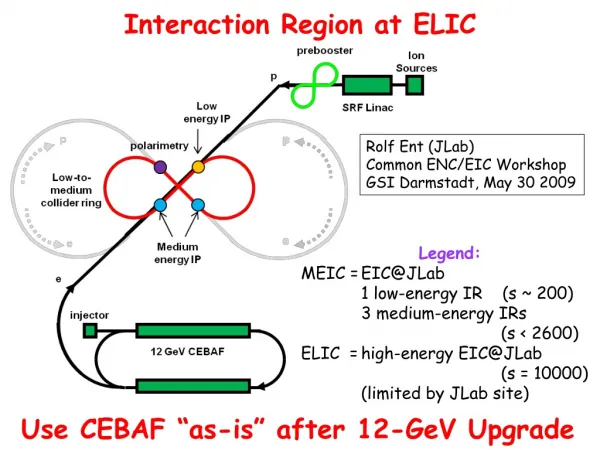
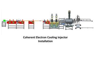
FormingIon Beams With Cooling SRF Linac cooling source To high energy ion collider ring (for Full Energy EIC@JLab) pre-booster-Accumulator ring Booster-low energy collider ring Medium energy ion collider ring Mature or state-of-art, except this
Stacking/cooling Ion Beam in Pre-booster/Accumulator Ring • Accumulation of 1 A coasted beam in pre-booster • Polarized p, d: stripping injection from negative ion source after linac • Other ions: must use DC electron cooling • Multi-turn (~10) pulse injection from linac • Damping/cooling of injected pulse • Accumulating beam at space charge limited emittance • Accelerating to 3 GeV/c • Fill large booster/low energy collider ring, then accelerate • Switch to collider ring for energy booster, • RF bunching and initial/continuous cooing Pre-booster/Accumulator-ring An advanced concept Overcoming space charge by accumulating low temperature, large area beam in ring with circular betatron modes
Initial, Final & Continuous Cooling of Ion Beam in ELIC Collider Ring
Design Choice of ELIC e-Cooler • Design Requirements and Challenges • Electron beam current • up to 3 A CW beam at 499 MHz repetition rate • About 5 nC bunch charge (possible space charge issue at low energy) • About 260 kC/day from source/injector (state-of-art is 0.2 kC/day) • Energy of cooling electron beam • up to 6.7 MeV for cooling low energy (12 GeV/c) ELIC • up to 33 MeV for cooling medium energy (60 GeV/c) ELIC • Beam power • Need 100 to 400 MW for cooling 60 to 250 GeV/c ELIC • Design Choice: ERL Circulator Cooler (ERL-CC) • Energy Recovery SRF Linac (ERL) to solve RF power problem • Circulator-cooler ring for reducing average current from source/ERL • ERL-CC can provide the required high cooling current while consuming low RF power! High Current & Lifetime of injector High RF Power
ERL Based Circulator e-Cooler solenoid ion bunch electron bunch Electron circulator ring Cooling section Fast beam kicker Fast beam kicker Circulator ring by-pass Path length adjustment (synchronization) energy recovery path SRF Linac electron injector dump
ELIC Cooler Design Parameters • Number of turns in circulator cooler ring is determined by degradation of electron beam quality caused by inter/intra beam heating up and space charge effect. • Space charge effect could be a leading issue when electron beam energy is low. • It is estimated that beam quality (as well as cooling efficiency) is still good enough after 100 to 300 turns in circulator ring. • This leads directly to a 100 to 300 times saving of electron currents from the source/injector and ERL.
Making of a cooling electron beam • A high bunch-charge and high repetition source/injector • Energy recovery linac • Fast kicker • Stability of cooling beam in a circulator ring • Single (electron) & coupled (electron-ion) instabilities • Long term space charge effect & beam quality degradation • Beam heat-up by IBS • Efficiency of cooling at medium ion energy • Cooling rate as a function of energy (state-of-art is 4 MeV at Fermilab) • Cooling efficiency as a function of turns in the circulator ring • Staged cooling (at injection & final energy, during collision) • New Concepts and Schemes • Flat-to-round beam transform and reduction of space charge effect Enabling Technologies and R&D
solenoids SRF modules 300keV DC gun buncher quads Electron Source/Injector • ELIC CCR driving injector • 10 mA@1.667 MHz, up to 33 (125) MeV energy • 5nC bunch charge, magnetized • Challenges • Source life time: 0.86kC/day (state-of-art is 0.2 kC/day) • source R&D, & exploiting possibility of increasing evolutions in CCR • Conceptual design • High current/brightness source/injector is a key issue of ERL based light source applications, much R&D has been done • We adopt light source injector as a baseline design of CCR driving injector • Beam qualities should satisfy electron cooling requirements (based on previous computer simulations/optimization) • Bunch compression may be needed.
Energy Recovery Linac JLab is world leader in ERL technology ! JLab FEL Program • SRF ERL based FEL • High average power, up to14 kW (world record) • mid-infrared spectral region • Extension to 250 nm in the UV is planned • Photocathode DC injector, 10 mA class CW beam, sub-nC bunch charge • Beam energy up to 200 MeV, energy recovery • Next proposal: 100kW average power, 100 mA CW beam. ERL, nC-class bunch charge Energy Recovery
Test Facility for Circulator Cooling Ring Transverse focusing lattice Diagnostic elements UsingJLab FEL ERL facility or a new SRF module fast kicker • A test facility for an ERL circulator cooler utilizing JLab FEL facility is under consideration. Additional hardware cost is moderate. • Focusing of this test facility will be studies of • Dynamics of electron beam in the circulator ring (space charge effect, single bunch instabilities, IBS heating up, etc.) • Lifetime of electron source/injector • test of fast kicker.
Ultra Fast RF Kicker • Goal: Development of a sub-ns pulse of 20 kW &15 MHz to drive a RF kicker • Leading candidate of a technical solution: • State-of-Art RF chirp technique is able to produce ~2 ns, 11 kW RF pulses at a 12 MHz repetition rate, very close to ELIC requirement. • Helically-corrugated waveguide (HCW) serves to further compress the output pulse without excessive loss. Up to 10 kW power have been created • Development plans include studies of HCW, optimization of chirp techniques, and generation of 1-2 kW peak output powers as proof of concept. (J. Musson, JLab, EE)
Ultra-Fast Beam-Beam Kicker • A short (1~ 3 cm) target electron bunch passes through a long (15 ~ 50 cm) low-energy flat bunch at a very close distance, receiving a transverse kick • The kicking force is • integrating it over whole kicking bunching gives the total transverse momentum kick • Proof-of-principle test of this fast kicker idea can be planned. Simulation studies will be initiated. F surface charge density v≈c h D kicking beam σc v0 L V. Shiltsev, NIM 1996
Advanced Cooling Concepts • Staged cooling • Start (longitudinal) electron cooling at injection energy in collider ring • Continue electron cooling after acceleration to high energy • Sweep cooling • After transverse stochastic cooling, ion beam has a small transverse temperature but large longitudinal one. • Use sweep cooling to gain a factor of longitudinal cooling time • Dispersive cooling • compensates for lack of transverse cooling rate at high energies due to large transverse velocity spread compared to the longitudinal (in rest frame) caused by IBS • Flat beam cooling (for high energies) • based on flattening ion beam by reduction of coupling around the ring • IBS rate at equilibrium reduced compared to cooling rate • Matched cooling (low energies) • based on use of circular modes optics of ions matched with solenoid of cooling section • separates cooling of beam temperature from cooling (round) beam area • results in removal temperature limit due to space charge (strong reduction of achievable 4D emittance)
Flat-to-Round Beam Transform & Reduction of Space Charge Effect • Flat colliding ion beam and space charge • Colliding ion beam should be flat at interaction point in order to match flat electron beam (due to synchrotron radiation) • Space charge tune shift is a leading limiting factor for low energy ion beam, and it further effect luminosity of the collider • Flat beam enhances space charge tune-shift . i.e., Laslett tune-shift is determined by smaller transverse dimension • Luminosity optimization: flat-to-round transform • if colliding ion beam can be arranged as • flat at interaction point matching flat electron beam • Round in the storage maintaining large transverse beam area for overcoming space charge • Technical feasibility • circular (100% coupled) optics (ring) under matched cooling • Special adapters to converting round beam to flat beam and back to round beam at collision point
Summary • ELIC Luminosity should be able to reach 4x1034 cm-2s-1 at medium energy range (60x3~5 GeV2) for e-p collisions, achieved through • high repetition CW electron and ion beam • very strong vertical final focusing (β*=5 mm) • very short bunch length (~5 mm) • Electron cooling is essential for forming (through stacking and accumulating) and cooling of the ion beam for ELIC. • Conceptual design of an ERL circulator cooler has been proposed to provide a high average current (3 A) cooling beam with energy up to 33 MeV. • Key enabling technologies includes electron source/injector, ERL, and ultra-fast kicker, either already existing or having promising conceptual designs. Thus cooler design is technical feasible. • Beam dynamics of circulating electron beam, cooling efficiency and design optimization are main R&D issues.
ELIC Study Group A. Afanasev, A. Bogacz, J. Benesch, P. Brindza, A. Bruell, L. Cardman, Y. Chao, S. Chattopadhyay, E. Chudakov, P. Degtiarenko, J. Delayen, Ya. Derbenev, R. Ent, P. Evtushenko, A. Freyberger, D. Gaskell, J. Grames, L. Harwood, T. Horn, A. Hutton, C. Hyde, R. Kazimi, F. Klein, G. A. Krafft, R. Li, L. Merminga, J. Musson, A. Nadel-Turonski, M. Poelker, R. Rimmer, C. Tengsirivattana, A. Thomas, M. Tiefenback, H. Wang, C. Weiss, B. Wojtsekhowski, B. Yunn, Y. Zhang - Jefferson Laboratory staffs and users W. Fischer, C. Montag - Brookhaven National Laboratory V. Danilov - Oak Ridge National Laboratory V. Dudnikov - Brookhaven Technology Group P. Ostroumov - Argonne National Laboratory V. Derenchuk - Indiana University Cyclotron Facility A. Belov - Institute of Nuclear Research, Moscow, Rssia V. Shemelin - Cornell University
ELIC Design Goals • Energy Wide CM energy range between 10 GeV and 100 GeV • High energy: up to 10GeVe on 250 GeVp or 100 GeV/n ion • Medium energy: up to 11 GeV e on 60 GeV p or 30 GeV/n ion • Low energy: 3 to 10 GeV e on 3 to 12 GeV/c p (and ion) • Luminosity • 1033 up to 1035 cm-2 s-1per interaction point • Multiple interaction points • Ion Species • Polarized H, D, 3He, possibly Li • Up to heavy ion A = 208, all striped • Polarization • Longitudinal at the IP for both beams, transverse of ions • Spin-flip of both beams • All polarizations >70% desirable • Positron Beamdesirable
EIC@JLab: Low to Medium Energy • Three compact rings: • 3 to 11 GeV electron • Up to 12 GeV/c proton (worm) • Up to 60 GeV/c proton (cold)
EIC@JLAB: Low to Medium Energy polarimetry
ELIC Ring-Ring Design Features • Unprecedented high luminosity • Electron cooling is an essential part of ELIC • Up to four IPs (detectors) for high science productivity • “Figure-8” ion and lepton storage rings • Ensure spin preservation and ease of spin manipulation • No spin sensitivity to energy for all species. • Present CEBAF injector meets storage-ring requirements • 12 GeV CEBAF can serve as a full energy injector to electron ring • Simultaneous operation of collider & CEBAF fixed target program. • Experiments with polarized positron beam are possible.
Circulator Ring & Synchronization Transverse focusing lattice • Bunch In/out kicking • An ultra fast kicker switches electron bunches in and out circulator ring. • Deflecting angle should be large enough to separate outgoing bunches from circulating bunches and be further deflected by a dipole • Duration of kicking should be less than bunch spacing (~1/500MHz = 2 ns) • Synchronization • Bunch spacing depends on beam energy. There is about 1.8 mm difference when energy is boosted from 12 to 60 GeV/c • A 10m dog-lag lattice or loops in arc must be introduced to ensure electron-ion synchronization at cooling section. • Maximum deflecting angle is 13º, providing total 26cm path length adjustment. Kicker Parameter