Network Topology and Geometry
230 likes | 440 Views
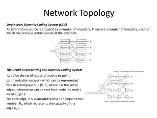
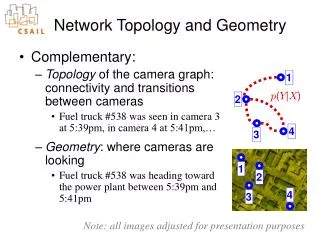
1. 2. 4. 3. Network Topology and Geometry. Complementary: Topology of the camera graph: connectivity and transitions between cameras Fuel truck #538 was seen in camera 3 at 5:39pm, in camera 4 at 5:41pm,… Geometry : where cameras are looking

Network Topology and Geometry
E N D
Presentation Transcript
1 2 4 3 Network Topology and Geometry • Complementary: • Topology of the camera graph: connectivity and transitions between cameras • Fuel truck #538 was seen in camera 3 at 5:39pm, in camera 4 at 5:41pm,… • Geometry: where cameras are looking • Fuel truck #538 was heading toward the power plant between 5:39pm and 5:41pm 1 p(Y|X) 2 4 3 Note: all images adjusted for presentation purposes
Motivating Scenario • Large network of cameras • I.e. hundreds or thousands • Location unknown, e.g. • Existing installations • Very rapid physical installation requirements • Regular traffic instrumented with GPS receivers (patrols, service vehicles, etc.) • …need to know camera locations
Cameras as Tripwires • This paper: • Narrow field-of-view (relative to GPS resolution) • Camera as a tripwire
Input Data (1) • Time instants when each camera observed a vehicle entering or exiting: {(tcj)} • Vehicle identity not known Time Camera
( ( ) ) l h l l @ l l i t t abbreviated as p p v a e c o n e a o n ; ; Input data (2) • GPS Tracks (5 vehicles): {(latvi, lonvi, tvi)} • Not known: when a particular vehicle is seen in a particular camera
( j ) ^ l l l l t t 2 p a o n a o n c a m e r a ; ; Estimation: What We Want …but, we don’t know when a specific instrumented vehicle is visible Camera location: probability (lat,lon) being in the field of view = p(vehicle being at (lat,lon) when the camera is tripped)
( ) ( j ) ( ) ^ l l l l l l 1 t t t ¡ 2 ® p a o n a o n c a m e r a p a o n ; ; ; ( ) 1 ¡ ® ( j ) l l l l ~ t t 2 p a o n a o n c a m e r a = ; ; Estimation: What We Get + ® = + ®
( ) 1 ¡ ® ( ( ) ( j j ) ) ( ) l l ^ l l l l l l l l ~ 1 t t t t t ¡ + 2 2 p a ® o p n a a o o n n a c a o m n e r a c a m e r a ® p a o n = ; ; ; ; ; Camera Sees Nothing = + ® GPS-instrumented vehicle Non-instrumented vehicle
( ) 1 ¡ ® ( ( ) ( j j ) ) ( ) l l ^ l l l l l l l l ~ 1 t t t t t ¡ + 2 2 p a ® o p n a a o o n n a c a o m n e r a c a m e r a ® p a o n = ; ; ; ; ; Camera Sees a GPS Vehicle = + ® GPS-instrumented vehicle Non-instrumented vehicle
( ) 1 ¡ ® ( ( ) ( j j ) ) ( ) l l ^ l l l l l l l l ~ 1 t t t t t ¡ + 2 2 p a ® o p n a a o o n n a c a o m n e r a c a m e r a ® p a o n = ; ; ; ; ; Camera Sees Nothing = + ® GPS-instrumented vehicle Non-instrumented vehicle
( ) 1 ¡ ® ( ( ) ( j j ) ) ( ) l l ^ l l l l l l l l ~ 1 t t t t t ¡ + 2 2 p a ® o p n a a o o n n a c a o m n e r a c a m e r a ® p a o n = ; ; ; ; ; Camera Sees a Distracter = + ® GPS-instrumented vehicle Non-instrumented vehicle
( ( ( ( ) ) ( j j ( ) j ) ) ) ( ) h l l ^ l l ^ h l l l l l l l l k l f k l l ~ ~ 1 t t t t t t t ¡ + ¿ 2 2 2 p p p a a ® o o p n n a p a a o o o n n n o a o c c a a o o m m n r e e p r r e a a a c a m s e r a ® p a o n ! = ; ; ; ; ; ; ; Best Cluster of Peaks
( ( j j ) ) ~ ~ p p x x y y c c ; ; Results Camera 2 Superimposed Results • Bright red squares: estimated camera fields of view • Dark red trapezoids: ground truth (rough) • Light green dots: peaks in • Dark green dots: non-peak votes in
Conclusions • No given correspondence • Topology • Tripwire data network topology and transitions • Can model appearance changes • Geometry • Tripwire data + GPS side information camera locations
Questions… Thank you
26.0 49.5 Estimated 65.0 40.5 Ground Truth 126.0 39.0 80.5 69.0 Location + Pose Voting Spaces • Conditioned on Traffic Direction Best Estimate Overlaid on a Satellite Map* * true satellite image substituted
Sample Simulated Network • 10 Cameras • Total road length: 4.2km • Mean speed: 60kph • 40 Intersections • 80 Roads • 8 Vehicles Rendering of Network (with one camera circled) Estimated (red) / Actual (green) Camera Location
Simulation Results Voting shape size
Calibration • Traditional calibration: • pixels ↔ object coordinates • Geodetic calibration: • pixels ↔ (latitude, longitude) • This paper: • Narrow field-of-view (relative to GPS resolution) • Camera as a tripwire
Why Not Just… …take a GPS reading on the camera? • It’s hard: GPS signals often blocked • It’s wrong: Need GPS readings of the imaged area, not of the camera …manually correspond image points to GPS readings? • Hazardous environments • Advertises boundaries of surveillance. • Does not scale well to hundreds or thousands of sensors that may be distributed very rapidly.