System Analysis & Design
System Analysis & Design. Chapter VI: Process Analysis and Modeling 1. Introduction

System Analysis & Design
E N D
Presentation Transcript
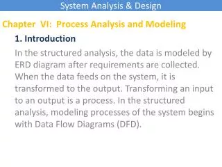
System Analysis & Design Chapter VI: Process Analysis and Modeling 1. Introduction In the structured analysis, the data is modeled by ERD diagram after requirements are collected. When the data feeds on the system, it is transformed to the output. Transforming an input to an output is a process. In the structured analysis, modeling processes of the system begins with Data Flow Diagrams (DFD).
System Analysis & Design Process A Chapter VI: Process Analysis and Modeling 2. Data Flow Diagrams DFDs, processes modeling tool, uses a number of symbols to present processes, data stores, data flows, and external entities in the system. 1 Data flow External entity Process B 2 Data store
System Analysis & Design Chapter VI: Process Analysis and Modeling 2. Data Flow Diagrams -Processes represent what the system does. Each process has one or more data input and produces one ore more data output. In DFD, a process represented by a circle. All processes have different names, and identification numbers. Check funding 1
System Analysis & Design Chapter VI: Process Analysis and Modeling 2. Data Flow Diagrams -Data stores are files to store the data. The data in the files can be read and written by the processes. Each data store is represented by a thin line. It has a unique name. Orders
System Analysis & Design Chapter VI: Process Analysis and Modeling 2. Data Flow Diagrams -Data flows show the flow of data in the system. It is represented by an arrow line that connects from one component to another component in the system. Data can flow between processes, external entities to processes, processes to processes, or processes to data stores and back. Receive customer order Enter into computer file 1 Accepted order 2
System Analysis & Design Chapter VI: Process Analysis and Modeling 2. Data Flow Diagrams -External entities are represented by rectangles. An external entity shows what are outside the system, but interact with the system. They might be a person who input data in to system or a person who use the output of the system. Customer
System Analysis & Design Spending summaries Delivery advice Management Chapter VI: Process Analysis and Modeling 3. Leveling DFD -Context diagram describes the system in general sense. Context diagram models the system by a single process. It shows all the external entities that interact with the system, and data flow between the external entities. Spending request Approval Departments Budget Monitoring System Confirmation Request for approval Book Order Budget allocation Delivery advice Suppliers
System Analysis & Design Chapter VI: Process Analysis and Modeling 2. Data Flow Diagrams The content diagram above models the Budget monitoring system. This system interact with three external entities: Departments, Management, and Supplier. The data flow from Departments is “Spending request”. The Departments receives confirmation (acceptation or rejection). The Management receives spending summaries and request for approval. The Management sends approval and budget allocation the system. The Suppliers get order from the system and send delivery advice to the system.
System Analysis & Design Leveling DFD allows you to start with a top-level function and break it to more detailed components. Chapter VI: Process Analysis and Modeling 3. Leveling DFD -Top level diagram shows more detail about the system. The major processes and data flows between them are described in Top level diagram.
System Analysis & Design Chapter VI: Process Analysis and Modeling 3. Leveling DFD -Lower level diagram expands the major processes described in the Top level diagram to provide more detail. For example, the process 3 can be further expanded to more detail sub processes. Each sub process is labeled with 3 followed by a number to show the expansion from process 3.
System Analysis & Design Accepted request A physical DFD Librarian checking book availability Chapter VI: Process Analysis and Modeling 4. Physical DFD Vs. Local DFD Physical DFD shows you how and who (person or computer) does the processes while a Logical DFD does not. Accepted request Enter to computer database file Database file Rejected request
System Analysis & Design A logical DFD Check book availability Chapter VI: Process Analysis and Modeling 4. Physical DFD Vs. Local DFD Physical DFD shows you how and who (person or computer) does the processes while a Logical DFD does not. Accepted request Borrowing request Book-loan list Rejected request
System Analysis & Design Chapter VI: Process Analysis and Modeling 5. Structure English To specify each process in DFD precisely so that it is understandable to the user and can be directly implemented , Structure English is used to achieve this objective. Structure English is like a programming language. However, it does have restrict syntax rules.
System Analysis & Design Chapter VI: Process Analysis and Modeling 5. Structure English To specify each process in DFD precisely so that it is understandable to the user and can be directly implemented , Structure English, Decision Table, or Decision Tree is used to achieve this objective. 5.1 Structure English Structure English is like a programming language. However, it does have restrict syntax rules. Operators that can be used in Structure English are: -Arithmetic: +,-,*,/ -Comparison: >,<,>=,<=,=,!= -Logical: and, or, not Beside the operators, there are a number of keywords that can be used: Begin, If, Then, Else, While, Do, Case, For, End, Until, Search, Read, Write, Repeat, Of.
System Analysis & Design Chapter VI: Process Analysis and Modeling 5. Structure English Decision: in Structure English to make a decision you can use IF, Else, and End If keywords. Example: If register on 01/02/13 Then If take >1 subject Then Discount 10% Else If pay advance Then Discount 5% Else No discount End if End if Else (register late) No discount End if
System Analysis & Design Chapter VI: Process Analysis and Modeling 5. Structure English Repetition: There are may ways to do repetition in Structure English: -For…Do -While…Do -Repeat…Until
System Analysis & Design Chapter VI: Process Analysis and Modeling 5. Structure English Example: max=list[0] For each next item in list Do If max<item Then max=item Print max
System Analysis & Design Chapter VI: Process Analysis and Modeling 5. Structure English Example: x=0 While x!=10 Do Print x x=x+1
System Analysis & Design Chapter VI: Process Analysis and Modeling 5. Structure English Example: i=0 Repeat Copy list[i] to list1[i] i=i+1 Until i>10
System Analysis & Design Chapter VI: Process Analysis and Modeling 5.2 Decision Table The Decision Table is also used to define a process specification. The Decision Table is first divided in to two parts: conditions and actions. An action is taken depending the combination of the conditions.
System Analysis & Design Chapter VI: Process Analysis and Modeling 5.2 Decision Table The Decision Table Example: Y=Yes, N=No X=do action
System Analysis & Design Discount 10% Take >1 subject Pay advance Discount 5% No discount Register on 01/02/13 5.3 Decision Tree Another tool to present the process specification is Decision Tree. Decision Tree Example: Not register on 01/02/13 No discount