Understanding Descriptive Geometry: Projections and Linear Measurements
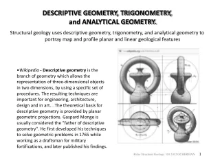
This guide explores the principles of descriptive geometry, focusing on the projection of three-dimensional figures into two-dimensional planes. It emphasizes the use of orthographic projections and auxiliary views to reveal true lengths, angles, shapes, and areas through graphical methods. Learn how to visualize lines and planes with respect to their true dimensions and discover practical applications of the Pythagorean theorem and slope measurements. Master essential techniques in descriptive geometry for effective geometric manipulations.

Understanding Descriptive Geometry: Projections and Linear Measurements
E N D
Presentation Transcript
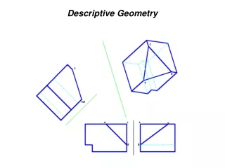
Descriptive Geometry • The projection of three-dimensional figures onto a two-dimensional plane of paper in a manner that allows geometric manipulations to determine lengths, angles, shapes, areas and other quantitative information by means of graphics. • Based on orthographic projections • Auxiliary views are used to show true lengths and point views of lines, true size and edge views of planes, angles between two lines, between two planes and between a line and a plane. • The Folding-Line Model can be used to visualize auxiliary views.
Point • A location in space • No dimension • Needs three coordinates (x,y,z) to define location in space: height (below H), width (left of P), depth (behind F) • Needs at least two views to show coordinates
Lines • Straight path between two points • A line can appear as: • foreshortened line • true-length line (TL) • point
Lines • Principal Line - parallel to at least one principal projection planes (H,F, P) • Oblique Line - neither parallel nor perpendicular to any principal plane • Principal Lines: • horizontal - parallel to H; TL in top view • frontal - parallel to F; TL in front view • profile - parallel to P; TL in side views
True Length of a Line • Pythagorean Theorem • True length diagram • Auxiliary View of the line Pythagorean Theorem
True Length of a Line True Length Diagram
True Length of a Line: Auxiliary View • Line of sight needs to be perpendicular to the line • But line of sight is perpendicular to the reference (or projection plane) • Therefore, reference plane must be parallel to the line. The resulting view will show the TL of the line.
Direction of a Line • Shown in the Top View • Compass Bearing • Angle measured from the N or S • angle is between 0 and 90 degrees • Azimuth • Angle measured clockwise from the north • angle is between 0 and 360 degrees
Slope of a Line • Measure of steepness/inclination with horizontal • Can be specified using • a. Slope = rise/run • b. %grade = slope × 100% • c. Slope angle • Angle between the TL of the line and the horizontal plane (H). • Find TL off the TV. The resulting view will show the angle between the TL of the line and the horizontal plane (corresponding to the H-ARP fold line).
Point-View of a Line Procedure: • 1. Find the true length of the line • a. Take a reference plane parallel to the line • b. Project the endpoints perpendicular to the reference plane. Label all reference planes. • c. Transfer distance away from “previous” corresponding reference plane • 2. Take a reference plane perpendicular to TL. • 3. Project and transfer. Line should be Ptview.
Edge View of a Plane - Find the Pt. View of any line in the plane. Procedure: • 1. Find a line in the plane that is shown as a TL. A. Draw a horizontal line 1-0 on the plane in the front view. B. The line in step A is TL in the top view. The desired line of sight is parallel to the TL line. • 2. Take a reference plane perpendicular to the located TL. • 3. The point view of line 1-0 is found by projecting from the top view. Locate 1 by transferring the dimension H from the front view. • 4. Locate points 2 and 3 by transferring their height dimensions from the front view. The plane should be EV.