1 / 0

ECE 3336 Introduction to Circuits & Electronics

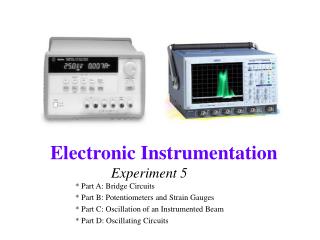
ECE 3336 Introduction to Circuits & Electronics. Lecture Set #10 Signal Analysis & Processing – Frequency Response & Filters. Dr. Han Le ECE Dept. Outline. Review Signal analysis Power spectral density Frequency response of a system (circuit) Transfer function Bode plot Filters

uta
Download Presentation

ECE 3336 Introduction to Circuits & Electronics

An Image/Link below is provided (as is) to download presentation Download Policy: Content on the Website is provided to you AS IS for your information and personal use and may not be sold / licensed / shared on other websites without getting consent from its author. Content is provided to you AS IS for your information and personal use only. Download presentation by click this link. While downloading, if for some reason you are not able to download a presentation, the publisher may have deleted the file from their server. During download, if you can't get a presentation, the file might be deleted by the publisher.

E N D

Presentation Transcript


  1. ECE 3336 Introduction to Circuits & Electronics Lecture Set #10 Signal Analysis & Processing – Frequency Response & Filters Dr. Han Le ECE Dept.
  2. Outline Review Signal analysis Power spectral density Frequency response of a system (circuit) Transfer function Bode plot Filters Analog Digital
  3. Concept Review: Signal Processing All electronics around us involve signal processing. Signal represents information. That information can be something we generate (e.g. texts, sounds, music, images) or from sensors. (discussion: examples of sensors) Electronics deal with signals: signal processing is to transform the signal and extract the desired information.
  4. Concept Review: Signal Processing (cont.) Signal processing is a general concept, not a single specific thing. It includes: signal synthesis or signal acquisition signal conditioning (transforming): shaping, filtering, amplifying signal transmitting signal receiving and analysis: transforming the signal, converting into information Signal processing is mathematical operation; electronics are simply tools. Computation is high-level signal processing: dealing directly with information rather than signal.
  5. Applications of mathematical techniques Harmonic function Fourier transform Signal and AC circuit problems RLC or any time-varying linear circuits. Applicable to linear portion of circuits that include nonlinear elements Signal processing signal analysis (spectral decomposition) filtering, conditioning (inc amplification) synthesizing Phasors Complex number &analysis Note: The main lecture material is in the Mathematica file – this is only for concept summary
  6. Homework (to be seen in HW 8) Choose an electronic system around you (e. g. a TV, DVD player, phone,…); show a functional block diagram and describe the signal processing sequence (end to end).
  7. Antenna Inductor Variable Capacitor Diode (1N34A) High-Impedance Earphone Ground Example
  8. Antenna Inductor Variable Capacitor Diode (1N34A) High-Impedance Earphone Ground Schematic Carrier wave Antenna (sound) signal Soundwave Electrical signal (voltage or current) Resonance circuit
  9. Link to Mathematica file: AM FM
  10. Outline Review Signal analysis Power spectral density Frequency response of a system (circuit) Transfer function Bode plot Filters Analog Digital
  11. Signal Fourier (or harmonic) Analysis Treat each time-finite signal as if it is composed of many harmonics, using Fourier series In complex (or Euler) representation, Fourier series coefficients Xm are phasor components,
  12. Signal Fourier (or harmonic) Analysis (cont) If the signal is real (all cases involving real physical quantity), then: Hence, we need to keep only positive frequencies A signal can be represented by a plot of |Xm| vs. frequency, or usually |Xm|2 if x(t) is voltage or current, known as the signal magnitude spectrum, or its power spectral density. Equally important is the phase spectrum: plot of fm vs. frequency
  13. Do not be confused between the word “spectrum” in the general English sense vs. specific definition of “spectrum” in power spectral density, or phase spectrum.
  14. The Electromagnetic Spectrum UV & solar blind Visible
  15. Example of Spectra
  16. Example of Spectra
  17. Outline Review Signal analysis Power spectral density Frequency response of a circuit Transfer function Bode plot Filters Analog Digital
  18. R C input vin[t] i(t) output vout[t] C i(t) R output vout[t] Example Frequency Response or, Frequency Transfer Function input vin[t]
  19. Frequency Transfer Function(Frequency Response Function) For many linear RLC circuits, the frequency response function usually has the form:
  20. Example: Test 1
  21. Bode Plot for Vout in Test 1
  22. Applications of Frequency Transfer Function Any signal can be decomposed as a sum of many phasors (Fourier components) For a linear system, each component can be multiplied by H[w] to obtain the output phasor The signal output is simply the sum of all the individual phasor (Fourier component) outputs.
  23. R C input vin[t] i(t) output vout[t] Example
  24. Outline Review Signal analysis Power spectral density Frequency response of a circuit Transfer function Bode plot Filters Analog Digital
  25. General Filter Concept Review This is a filter This is also filter This is another filter
  26. General Filter Concept A system (electronic circuit) can be designed such that its transfer function H[w] has preference (let through) certain ranges of frequencies while attenuating (blocking) other frequencies Such a circuit is called a filter. Filter is a concept about the function of a circuit, not the circuit itself. Filter includes both amplitude response and phase shift. Usually, only amplitude is plotted.
  27. Common Types of Filters High pass filter Band pass filter Band stop (notch) filter Low pass filter
  28. Design of Filters A circuit designed to perform filtering function on an analog signal is called an analog filter. If a signal is digital (converted into a sequence of number), a filter can be realized as a mathematical operation, this is called digital filter. Digital filter can be done with any computing device: from a DSP chip to a computer.
  29. Example of Simple Analog Filters RC band stop filter. RC bandpass filters
  30. Example of Simple Analog Filters RLC resonant filter
  31. Example of Simple Analog Filters Notch filter application: rejection line 60-Hz signal
  32. Example: Test 1 Notch Filter
  33. Example: Test 1: Bandpass Filter
  34. Digital Filter Any filter function can be achieved with digital filter Signal input Filtered signal output Micro-processor (DSP) User input
  35. Digital Filter Digital filter can also be designed with sharp cut-off edge that is difficult with analog filter.
  36. http://www2.renesas.com/linear/en/application/equipment/cd.html http://www2.renesas.com/linear/en/application/equipment/cd.html
  37. From TI http://focus.ti.com/docs/solution/folders/print/530.html
More Related