Download
1 / 47
550 likes | 1.63k Views
CHAPTER 9 Lubrication System Operation and Diagnosis. OBJECTIVES. After studying Chapter 9, the reader will be able to: Prepare for Engine Repair (A1) ASE certification test content area “D” (Lubrication and Cooling Systems Diagnosis and Repair). Explain engine oil ratings.

E N D
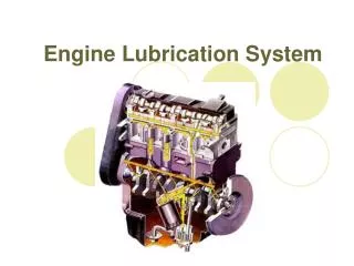
CHAPTER 9 Lubrication System Operation and Diagnosis
OBJECTIVES After studying Chapter 9, the reader will be able to: • Prepare for Engine Repair (A1) ASE certification test content area “D” (Lubrication and Cooling Systems Diagnosis and Repair). • Explain engine oil ratings. • Describe how an oil pump and engine lubrication work. • Discuss how and when to change the oil and filter. • Explain how to inspect an oil pump for wear.
boundary lubrication Hydrodynamic lubrication Longitudinal header oil gallery positive displacement pump pressure regulating valve viscosity windage tray KEY TERMS
LUBRICATION PRINCIPLES • Engine oil is the lifeblood of any engine. • The purposes of engine oil include the following: • Lubricating all moving parts to prevent wear • Helping to cool the engine • Helping to seal piston rings • Cleaning, and holding dirt in suspension in the oil until it can be drained from the engine • Neutralizing acids that are formed as the result of the combustion process • Reducing friction • Preventing rust and corrosion
FIGURE 9–1 Oil molecules cling to metal surfaces but easily slide against each other. LUBRICATION PRINCIPLES • Lubrication between two moving surfaces results from an oil film that separates the surfaces and supports the load.
FIGURE 9–2 Wedge-shaped oil film developed below a moving block. LUBRICATION PRINCIPLES
FIGURE 9–3 Wedge-shaped oil film curved around a bearing journal. LUBRICATION PRINCIPLES
ENGINE LUBRICATION SYSTEMS • The primary function of the engine lubrication system is to maintain a positive and continuous oil supply to the bearings. • Engine oil pressure must be high enough to get the oil to the bearings with enough force to cause the oil flow that is required for proper cooling. • The normal engine oil pressure range is from 10 to 60 PSI (200 to 400 kPa) (10 PSI per 1000 engine RPM). • However, hydrodynamic film pressures developed in the high-pressure areas of the engine bearings may be over 1,000 PSI (6,900 kPa). • The relatively low engine oil pressures obviously could not support these high bearing loads without hydrodynamic lubrication.
FIGURE 9–4 An oil pump driven by the camshaft. OIL PUMPS • All production automobile engines have a full-pressure oil system. • The oil is drawn from the bottom of the oil pan and is forced into the lubrication system under pressure. • In most engines that use a distributor, the distributor drive gear meshes with a gear on the camshaft.
FIGURE 9–5 The operation of a rotor-type oil pump. OIL PUMPS
FIGURE 9–6 A typical oil pump mounted in the front cover of the engine that is driven by the crankshaft. OIL PUMPS
FIGURE 9–7 Gerotor-type oil pump driven by the crankshaft. OIL PUMPS
FIGURE 9–8 In a gear-type oil pump, the oil flows through the pump around the outside of each gear. This is an example of a positive displacement pump, where everything entering the pump must leave the pump. OIL PUMPS
OIL PRESSURE REGULATION • In engines with a full-pressure lubricating system, maximum pressure is limited with a pressure relief valve. • The relief valve (sometimes called the pressure regulating valve) is located at the outlet of the pump. • The relief valve controls maximum pressure by bleeding off oil to the inlet side of the pump.
FIGURE 9–9 Oil pressure relief valves are spring loaded. The stronger the spring tension, the higher the oil pressure. OIL PRESSURE REGULATION
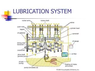
FIGURE 9–10 A typical engine design that uses both pressure and splash lubrication. Oil travels under pressure through the galleries (passages) to reach the top of the engine. Other parts are lubricated as the oil flows back down into the oil pan or is splashed onto parts. OIL PRESSURE REGULATION
FACTORS AFFECTING OIL PRESSURE • As the engine parts wear and clearance becomes greater, more oil will leak out. • The oil pump capacity must be great enough to supply extra oil for these leaks. • The capacity of the oil pump results from its size, rotating speed, and physical condition. • If the pump is rotating slowly as the engine is idling, oil pump capacity is low. • If the leaks are greater than the pump capacity, engine oil pressure is low.
FACTORS AFFECTING OIL PRESSURE • The viscosity of the engine oil affects both the pump capacity and the oil leakage. • Thin oil or oil of very low viscosity slips past the edges of the pump and flows freely from the leaks. • Hot oil has a low viscosity, and therefore, a hot engine often has low oil pressure. • Cold oil is more viscous (thicker) than hot oil. • This results in higher pressures, even with the cold engine idling.
FACTORS AFFECTING OIL PRESSURE • High oil pressure occurs with a cold engine, because the oil relief valve must open farther to release excess oil than is necessary with a hot engine. • This larger opening increases the spring compression force, which in turn increases the oil pressure. • Putting higher-viscosity oil in an engine will raise the engine oil pressure to the regulated setting of the relief valve at a lower engine speed.
OIL PUMP CHECKS • The cover is removed to check the condition of the oil pump. • The gears and housing are examined for scoring. • If the gears and housing are heavily scored, the entire pump should be replaced. • If they are lightly scored, the clearances in the pump should be measured.
FIGURE 9–11 (a) A visual inspection indicated that this pump cover was worn. (b) An embedded particle of something was found on one of the gears, making this pump worthless except for scrap metal. OIL PUMP CHECKS
FIGURE 9–12 (a) The oil pump is the only part in an engine that gets unfiltered engine oil. The oil is drawn up from the bottom of the oil pan and is pressurized before flowing to the oil filter. (b) If debris gets into an oil pump, the drive or distributor shaft can twist and/or break. When this occurs, the engine will lose all oil pressure. OIL PUMP CHECKS
OIL PASSAGES IN THE BLOCK • From the filter, oil goes through a drilled hole that intersects with a drilled main oil gallery or longitudinal header. • This is a long hole drilled from the front of the block to the back. • Inline engines use one oil gallery; V-type engines may use two or three galleries. • Passages drilled through the block bulkheads allow the oil to go from the main oil gallery to the main and cam bearings.
FIGURE 9–13 An intermediate shaft drives the oil pump on this overhead camshaft engine. Note the main gallery and other drilled passages in the block and cylinder head. OIL PASSAGES IN THE BLOCK
VALVE TRAIN LUBRICATION • The valve train components are the last parts to get oil from the oil pump. • The oil gallery may intersect or have drilled passages to the valve lifter bores to lubricate the lifters. • When hydraulic lifters are used, the oil pressure in the gallery keeps refilling them. • On some engines, oil from the lifters goes up the center of a hollow pushrod to lubricate the pushrod ends, the rocker arm pivot, and the valve stem tip.
FIGURE 9–14 Oil is sent to the rocker arms on this Chevrolet V-8 engine through the hollow pushrods. The oil returns to the oil pan through the oil drainback holes in the cylinder head. VALVE TRAIN LUBRICATION
OIL PANS • As the vehicle accelerates, brakes, or turns rapidly, the oil tends to move around in the pan. • Pan baffles and oil pan shapes are often used to keep the oil inlet under the oil at all times. • As the crankshaft rotates, it acts like a fan and causes air within the crankcase to rotate with it. • A baffle or windage tray is sometimes installed in engines to eliminate the oil churning problem. This may be an added part,
FIGURE 9–15 A typical oil pan with a built-in windage tray used to keep oil from being churned up by the rotating crankshaft. OIL PANS
FIGURE 9–16 A straightedge and a feeler gauge are being used to check that the oil pan has been correctly installed on the 5.7-liter Chevrolet V-8 engine. The oil pan is part of the engine itself and must be properly installed to ensure that other parts attached to the engine are not being placed in a bind. OIL PANS
FIGURE 9–17 A typical engine oil cooler. Engine coolant flows through the cooler adjuster that fits between the engine block and the oil filter. OIL COOLERS • Oil temperature must also be controlled on many highperformance or turbocharged engines.
OIL PRESSURE WARNING LAMP • All vehicles are equipped with an oil pressure gauge or a warning lamp. • The warning lamp comes on whenever the engine oil pressure has dropped to 3 to 7 PSI. • Normal oil pressure is considered to be 10 PSI per 1,000 RPM. • An electrical switch is used to convert the ground circuit of the oil pressure warning lamp if the oil pressure is below the rating of the sending unit.
FIGURE 9–18 The oil pressure switch is connected to a warning lamp that alerts the driver of low oil pressure. OIL PRESSURE WARNING LAMP
FIGURE 9–19 A typical oil pressure sending unit on a Ford V-8. OIL PRESSURE WARNING LAMP
What Is Acceptable Oil Consumption? • There are a number of opinions regarding what is acceptable oil consumption. Most vehicle owners do not want their engine to use any oil between oil changes even if they do not change it more often than every 7,500 miles (12,000 kilometers). Engineers have improved machining operations and piston ring designs to help eliminate oil consumption. • Many stationary or industrial engines are not driven on the road; therefore, they do not accumulate miles, yet they still may consume excessive oil. • A general rule for “acceptable” oil consumption is that it should be about 0.002 to 0.004 pounds per horsepower per hour.
What Is Acceptable Oil Consumption? • Therefore, oil consumption is based on the amount of work an engine performs. Although the formula may not be usable for vehicle engines used for daily transportation, it may be usable by the marine or industrial engine builder. Generally, oil consumption that is greater than 1 quart for every 600 miles (1,000 kilometers per liter) is considered to be excessive with a motor vehicle.
SUMMARY • Normal engine oil pump pressure ranges from 10 to 60 PSI (200 to400 kPa) or 10 PSI for every 1000 engine RPM. • Hydrodynamic oil pressure around engine bearings is usually over 1,000 PSI (6,900 kPa). • The oil pump is driven directly by the crankshaft or by a gear or shaft from the camshaft. • The last components to get oil from the oil pump are the valve train parts. • Some engines use an oil cooler.
REVIEW QUESTIONS • What causes a wedge-shaped film to form in the oil? • What is hydrodynamic lubrication? • Explain why internal engine leakage affects oil pressure. • Describe how the oil flows from the oil pump, through the filter and main engine bearings, to the valve train. • What is the purpose of a windage tray?
CHAPTER QUIZ 1. Normal oil pump pressure in an engine is ________. • 3 to 7 PSI • 10 to 60 PSI • 100 to 150 PSI • 180 to 210 PSI
CHAPTER QUIZ 2. The oil pump pressure relief valve is also called ________. • Oil pump valve • Pressure valve • Pressure regulating valve • Pressure dump valve
CHAPTER QUIZ 3. A typical oil pump is what type of pump? • Positive displacement • Centrifugal • Piston-type • Hydraulically driven
CHAPTER QUIZ 4. Engine oil passages in an engine block are called ________. • Oil passages • Oil galleries • Weep holes • Oil holes
CHAPTER QUIZ 5. Technician A says that the oil pump draws unfiltered oil from the bottom of the oil pan. Technician B says that the oil pump is driven from the front of the crankshaft in some engines. Which technician is correct? • Technician A only • Technician B only • Both Technicians A and B • Neither Technician A nor B
CHAPTER QUIZ 6. Technician A says that oil pressure is affected by the amount of main and rod bearing clearance. Technician B says that the oil pressure is lower when the oil gets hot than when it is cold. Which technician is correct? • Technician A only • Technician B only • Both Technicians A and B • Neither Technician A nor B
CHAPTER QUIZ 7. Technician A says that many engines use a windage tray in the oil pan. Technician B says that some engines are equipped with an oil cooler. Which technician is correct? • Technician A only • Technician B only • Both Technicians A and B • Neither Technician A nor B
CHAPTER QUIZ 8. The oil pressure warning light normally comes on to warn the driver if the oil pressure drops below ________. • 50 PSI • 30 PSI • 10 PSI • 3 to 7 PSI
CHAPTER QUIZ 9. A typical oil pump can pump how many gallons per minute? • 3 to 6 gallons • 6 to 10 gallons • 10 to 60 gallons • 50 to 100 gallons
CHAPTER QUIZ 10. In typical engine lubrication systems, what components are the last to receive oil and the first to suffer from a lack of oil or oil pressure? • Main bearings • Rod bearings • Valve train components • Oil filters