Flow Devices
Flow Devices. Thermodynamics Professor Lee Carkner Lecture 10. PAL # 9 Control Volumes. Air flow through pipe Find diameter from area, find area from mass flow rate (= r AV) v = RT/P = (0.287)(350)/(300) = A = m’ v /V = (18/60)(0.3349)/(25) = 0.004018 m 2

Flow Devices
E N D
Presentation Transcript
Flow Devices Thermodynamics Professor Lee Carkner Lecture 10
PAL # 9 Control Volumes • Air flow through pipe • Find diameter from area, find area from mass flow rate (=rAV) • v = RT/P = (0.287)(350)/(300) = • A = m’v/V = (18/60)(0.3349)/(25) = 0.004018 m2 • D = (4A/p)½ = (4(0.004018) / p)½ =
PAL # 9 Control Volumes • Rate of flow energy = m’Pv • W’flow = (18/60)(300)(0.3349) = • Energy transport by mass: • E’mass = m’(h+ke) = m’(cpT + ½V2) • E’mass = (18/60)[(1.008)(350) + (½)(25)2(1/1000)] = • Neglecting ke • E’mass = m’h = m’cpT = (18/60)(1.005)(350) = 105.84 kW
Steady-Flow Devices • Emass,in = Emass,out W’in + Q’in + m’in(h + V2/2 + gz)in = W’out + Q’out + m’out(h + V2/2 + gz)out • but mass and energy are conserved in each
Nozzles V’1 = V’2 V1A1 = V2A2 V1/V2 = A2/A1 • Velocity changes opposite to pipe diameter change • Small to large opening, velocity decreases, diffuser • But basic idea holds for gases
Working With Nozzles • Nozzles increase velocity at the expense of pressure • Other energies usually negligible • Can often use ideal gas law and enthalpy tables to solve problems • n.b. • Simplified nozzle equation • h1+½V21 = h2+½V22
Turbines • The flow work pushes the fluid into a control volume • Change enthalpy into work • Change work into enthalpy • Q ~ DPE ~ 0
Working with Turbines • but the change in kinetic energy is normally small compared to enthalpy change • Simplified turbine equation: • W’ = m’(Dh + Dke)
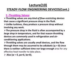
Throttling Valve • A throttling valve restricts flow causing a pressure drop • So conservation of energy gives us h1 = h2 • A throttling process shifts energy between internal and flow energies • Simplified throttling equation: • u1 + P1v1 = u2 + P2v2
Mixing Chamber • Usually Q ~ W ~ DKE ~ DPE ~ 0 • Simplified mixing chamber equations: • m’1 + m’2 = m’3 • m’1h1 + m’2h2 = m’3h3
Heat Exchanger • Generally, W ~ DPE ~ DKE ~ 0 • This means that mass flow and enthalpy are the only important variables
Working With Heat Exchangers • Fluid B enters at 3 and exits at 4 • Mass conservation: • m’3 = m’4 = m’B • Energy conservation • Simplified heat exchanger equation: • m’A (h1-h2) = m’B(h4-h3)
Unsteady Flow • Unsteady flow involves changes within the control volume • Example: • Mass within the flow volume increases • Deal with changes in properties with time rather than rates
Uniform Flow • If the input and output flow is steady and only the properties of the control volume change, it is a uniform flow process Q-W = (mh)out – (mh)in + (m2u2-m1u1)system • Where: • mh is the sum of all the enthalpies in or out
Next Time • No class Friday • For Monday: • Read: 6.1-6.4 • Homework: tba


![Blood Flow Measurement Devices Market Report [2016-2021]](https://cdn5.slideserve.com/9793343/blood-flow-measurement-devices-market-worth-dt.jpg)