Download
1 / 19
250 likes | 643 Views
Lecture(10) STEADY-FLOW ENGINEERING DEVICES(Cont.). 3 -Throttling Valves :. Throttling valves are any kind of flow-restricting devices that cause a significant pressure drop in the fluid. Unlike turbines, they produce a pressure drop without involving any work.

E N D
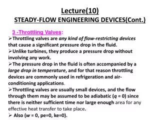
Lecture(10)STEADY-FLOW ENGINEERING DEVICES(Cont.) 3 -Throttling Valves: • Throttling valves are any kind of flow-restricting devices that cause a significant pressure drop in the fluid. • Unlike turbines, they produce a pressure drop without involving any work. • The pressure drop in the fluid is often accompanied by a large drop in temperature, and for that reason throttling devices are commonly used in refrigeration and air-conditioning applications. • Throttling valves are usually small devices, and the flow through them may be assumed to be adiabatic (q ≈ 0) since there is neither sufficient time nor large enough area for any effective heat transfer to take place. • Also (w = 0, pe=0, ke=0).
Then the conservation of energy equation for this single-stream steady-flow device reduces to: • Then: • Thus the final outcome of a throttling process depends on which of the two quantities increases during the process. • If the flow energy increases during the process (P2v2 > P1v1), it can do so at the expense of the internal energy. • If the product Pvdecreases, the internal energy and the temperature of a fluid will increase during a throttling process. • In the case of an ideal gas, h = h(T ), and thus the temperature has to remain constant during a throttling process.
Fig .(3.1) EXAMPLE 10.1
Mixing chambers are usually well insulated (q ≈ 0) and usually do not involve any kind of work (w= 0). Also, the kinetic and potential energies of the fluid streams are usually negligible (ke = 0, pe = 0). • Then all there is left in the energy equation is the total energies of the incoming streams and the outgoing mixture. • The conservation of energy principle requires that these two equal each other. • Therefore, the conservation of energy equation becomes analogous to the conservation of mass equation for this case.
Example (10-2) Solution: In a shower, cold water is mixed with hot water at a specified temperature. For a specified mixture temperature, the ratio of the mass flow rates of the hot to cold water is to be determined
Assumptions 1 This is a steady-flow process since there is no change with time at any point and thus mCV 0 and ECV 0. 2 The kinetic and potential energies are negligible, kepe 0. 3 Heat losses from the system are negligible and thus Q = 0. 4 There is no work interaction involved. Analysis: We take the mixing chamber as the system (Fig. 5–33). This is a control volume since mass crosses the system boundary during the process. We observe that there are two inlets and one exit. Under the stated assumptions and observations, the mass and energy balances for this steady-flow system can be expressed in the rate form as follows:
5-Heat Exchangers • heat exchangers are devices where two moving fluid streams exchange heat without mixing. • Heat exchangers are widely used in various industries, and they come in various designs. • The simplest form of a heat exchanger is a double-tube (also called tube and-shell) heat exchanger is composed of two concentric pipes of different diameters. • One fluid flows in the inner pipe, and the other in the annular space between the two pipes. • Heat is transferred from the hot fluid to the cold one through the wall separating them. Sometimes the inner tube makes a couple of turns inside the shell to increase the heat transfer area, and thus the rate of heat transfer. The mixing chambers discussed earlier are sometimes classified as direct-contact heat exchangers.
The conservation of mass principle for a heat exchanger in steady operation requires that the sum of the inbound mass flow rates equal the sum of the outbound mass flow rates. This principle can also be expressed as follows: Under steady operation, the mass flow rate of each fluid stream flowing through a heat exchanger remains constant.. EXAMPLE (10-3) Refrigerant-12 is to be cooled by water in a condenser. The refrigerant enters the condenser with a mass flow rate of 6 kg/min at 1 MPa and 70°C and leaves at 35°C. The cooling water enters at 300 kPa and 15°C and leaves at 25°C. Neglecting any pressure drops, determine (a) the mass flow rate of the cooling water required and (b) the heat transfer rate from the refrigerant to water.