Distributed Power Flow Controller by using Modern Facts Devices
70 likes | 93 Views
This Paper deals with a new concept within the Flexible AC Transmission System FACTS family, called Distributed Power Flow Controller DPFC , is the most powerful FACTS device, which can simultaneously control all the parameters of the system like the line impedance, the transmission angle, and bus voltage. The DPFC is derived from the Unified Power Flow Controller UPFC . But there is a drawback in UPFC that is the components of the UPFC handle the voltages and currents with high rating, therefore the total cost of the system is high. Due to the common dc link interconnection, a failure that happens at one converter will influence the whole system. To achieve the required reliability for power systems, bypass circuits and redundant backups backup transformers, capacitor Banks etc. are needed, which on other hand, increase the cost. Accordingly, the UPFC has not been commercially used, even though it has the most advanced control capabilities. DPFC uses one shunt and several series converters. The shunt converter is similar as a STATCOM, the series converter of the DPFC employs the Distributed FACTS concept, which uses multiple small single phase converters instead of one large size converter. The common dc link between the shunt and series converters, which is used for exchanging active power in the UPFC, is eliminated in case of DPFC. This power is now transmitted through the transmission line at the Third harmonic frequency. Shaik Abid | C. Dinakaran "Distributed Power Flow Controller by using Modern Facts Devices" Published in International Journal of Trend in Scientific Research and Development (ijtsrd), ISSN: 2456-6470, Volume-4 | Issue-1 , December 2019, URL: https://www.ijtsrd.com/papers/ijtsrd29617.pdf Paper URL: https://www.ijtsrd.com/engineering/electrical-engineering/29617/distributed-power-flow-controller-by-using-modern-facts-devices/shaik-abid<br>

Distributed Power Flow Controller by using Modern Facts Devices
E N D
Presentation Transcript
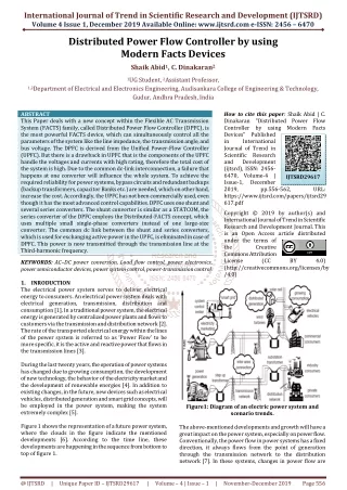
International Journal of Trend in Scientific Research and Development (IJTSRD) Volume 4 Issue 1, December 2019 Available Online: www.ijtsrd.com e-ISSN: 2456 – 6470 Distributed Power Flow Controller by using Modern Facts Devices Shaik Abid1, C. Dinakaran2 1UG Student, 2Assistant Professor, 1,2Department of Electrical and Electronics Engineering, Audisankara College of Engineering & Technology, Gudur, Andhra Pradesh, India ABSTRACT This Paper deals with a new concept within the Flexible AC Transmission System (FACTS) family, called Distributed Power Flow Controller (DPFC), is the most powerful FACTS device, which can simultaneously control all the parameters of the system like the line impedance, the transmission angle, and bus voltage. The DPFC is derived from the Unified Power-Flow Controller (UPFC). But there is a drawback in UPFC that is the components of the UPFC handle the voltages and currents with high rating, therefore the total cost of the system is high. Due to the common dc-link interconnection, a failure that happens at one converter will influence the whole system. To achieve the required reliability for power systems, bypass circuits and redundant backups (backup transformers, capacitor Banks etc.) are needed, which on other hand, increase the cost. Accordingly, the UPFC has not been commercially used, even though it has the most advanced control capabilities. DPFC uses one shunt and several series converters. The shunt converter is similar as a STATCOM, the series converter of the DPFC employs the Distributed-FACTS concept, which uses multiple small single-phase converters instead of one large-size converter. The common dc link between the shunt and series converters, which is used for exchanging active power in the UPFC, is eliminated in case of DPFC. This power is now transmitted through the transmission line at the Third-harmonic frequency. KEYWORDS: AC–DC power conversion, Load flow control, power electronics, power semiconductor devices, power system control, power-transmission control. 1.INRODUCTION The electrical power system serves to deliver electrical energy to consumers. An electrical power system deals with electrical generation, transmission, distribution and consumption [1]. In a traditional power system, the electrical energy is generated by centralized power plants and flows to customers via the transmission and distribution network [2]. The rate of the transported electrical energy within the lines of the power system is referred to as ‘Power Flow’ to be more specific, it is the active and reactive power that flows in the transmission lines [3]. During the last twenty years, the operation of power systems has changed due to growing consumption, the development of new technology, the behavior of the electricity market and the development of renewable energies [4]. In addition to existing changes, in the future, new devices such as electrical vehicles, distributed generation and smart grid concepts, will be employed in the power system, making the system extremely complex [5]. Figure 1 shows the representation of a future power system, where the clouds in the figure indicate the mentioned developments [6]. According to the time line, these developments are happening in the sequence from bottom to top of figure 1. How to cite this paper: Shaik Abid | C. Dinakaran "Distributed Power Flow Controller by using Modern Facts Devices" Published in International Journal of Trend in Scientific Research and Development (ijtsrd), ISSN: 2456- 6470, Volume-4 | Issue-1, December 2019, pp.556-562, https://www.ijtsrd.com/papers/ijtsrd29 617.pdf Copyright © 2019 by author(s) and International Journal of Trend in Scientific Research and Development Journal. This is an Open Access article distributed under the terms of the Creative Commons Attribution License (CC (http://creativecommons.org/licenses/by /4.0) IJTSRD29617 URL: BY 4.0) Figure1: Diagram of an electric power system and scenario trends. The above-mentioned developments and growth will have a great impact on the power system, especially on power flow. Conventionally, the power flow in power systems has a fixed direction, it always flows from the point of generation through the transmission network to the distribution network [7]. In these systems, changes in power flow are @ IJTSRD | Unique Paper ID – IJTSRD29617 | Volume – 4 | Issue – 1 | November-December 2019 Page 556
International Journal of Trend in Scientific Research and Development (IJTSRD) @ www.ijtsrd.com eISSN: 2456-6470 scheduled based on hours, not more frequently. However, due to the trends listed above, newer systems with greater capabilities are already being put to use, power flow can be bidirectional and variations can occur in minutes or even seconds [8]. A combined device is a two-port device that is connected to the grid, both as a shunt and in a series, to enable active power exchange between the shunt and series parts. Combined devices are suitable for power flow control because they can simultaneously vary multiple system parameters, such as the transmission angle, the bus voltage magnitude and the line impedance. Normally, the High Voltage DC transmission (HVDC) and PE devices that are applied at the distribution network, such as a Dynamic Voltage Restorer (DVR), are also considered as FACTS controllers are represented in figure 4. Most of the FACTS controllers can be used for power flow control. However, the HVDC and the DVR are out of the scope of the PFCD. The relationship between the PFCDs, FACTS controllers and mechanical controller is shown in figure 5. Figure2: Relation chart of the trends and their impact on the power flow Figure 2 illustrates the impact of these new trends on the power flow. Distributed Generation (DG) takes place at small and medium power generators that are connected to the distribution side of the power system [9]. Many DG units are based on renewable energy sources such as solar and wind. Driven by government policies aimed at reducing greenhouse gas emissions and conserving fossil fuels, as agreed by the Kyoto protocol, the number of grid-connected DG units is increasing [10]. Introducing a number of generators on the distribution side leads to big changes of the power flow in networks. 2.POWER FLOW CONTROLLING DEVICES Power flow is controlled by adjusting the parameters of a system, such as voltage magnitude, line impedance and transmission angle. The device that attempts to vary system parameters to control the power flow can be described as a Power Flow Controlling Device (PFCD). Depending on how devices are connected in systems, PFCDs can be divided into shunt devices, series devices, and combined devices (both in shunt and series with the system), as shown in figure 3. Figure4: Relationship between the PFCDs, FACTS controllers and mechanical Controller Figure5: Control range of active and reactive power flows with vary θ and X TCR employs the firing angle control to the Thyristors to vary the current thereby controlling the shunt reactance of the TCR. The firing angle varies from a 90◦ delay, for continuous conduction to 180◦ delay, for minimum conduction, as shown in Figure 6. A TCR combined with TSCs is able to provide continuously variable VAR injection or absorption. Figure3: Simplified diagram of shunt, series and combined devices A shunt device is a device that connects between the grid and the ground. Shunt devices generate or absorb reactive power at the point of connection thereby controlling the voltage magnitude. Because the bus voltage magnitude can only be varied within certain limits, controlling the power flow in this way is limited and shunt devices mainly serve other purposes. For example, the voltage support provided by a shunt device at the midpoint of a long transmission line can boost the power transmission capacity. Figure6: Voltage and current waveforms of a TCR for different firing angles @ IJTSRD | Unique Paper ID – IJTSRD29617 | Volume – 4 | Issue – 1 | November-December 2019 Page 557
International Journal of Trend in Scientific Research and Development (IJTSRD) @ www.ijtsrd.com eISSN: 2456-6470 3.STATCOM A static synchronous compensator (STATCOM) is basically a VSC that is connected between a grid and the ground through a coupling inductance, as shown in figure 7. The STATCOM acts as an AC voltage source and has characteristics similar to a synchronous condenser (A synchronous generator that is running idle and used for reactive compensation). The STATCOM injects an AC current in Quadrature (leading or lagging) with the grid voltage, and emulates capacitive or inductive impedance at the point of connection. If the voltage generated by the STATCOM is less than the grid voltage, it will act as an inductive load and withdraw reactive powers from the system. Conversely, when the STATCOM voltage is higher than the grid voltage, it will act as a capacitor load and provide reactive power to the grid. Compared to the synchronous condenser, the STATCOM is a PE-based device without inertia and therefore has a faster dynamic response. It consists of a three-phase current-fed converter, whose outputs are connected to a three-phase full-bridge diode rectifier through a delta-delta wound three- phase transformer. The three-phase current-fed converter is divided into a three-phase full-bridge converter configured as six main MOSFET switches (S1–S6) for three-phase dc/ac conversion, one auxiliary MOSFET switch (Sc) and clamp capacitor Cc for the active clamp and a dc boost inductor Ldc acting as a current source. 4.DISTRIBUTED POWER FLOW CONTROLLER (DPFC) After studying the failure mode of the combined FACTS devices, it is found that a common DC link between converters reduces the reliability of a device, because a failure in one converter will pervade the whole device though the DC link. By eliminating this DC link, the converters within the FACTS devices are operated independently, thereby increasing their reliability. The elimination of the common DC link also allows the Distributed Static Series Compensator concept to be applied to series converters. In that case, the reliability of the new device is further improved due to the redundancy provided by the distributed series converters. In addition, series converter distribution reduces cost because no high-voltage isolation and high power rating components are required at the series part. By applying the two approaches i.e., eliminating the common DC link and distributing the series converter, the UPFC is further developed into a new combined FACTS device, the Distributed Power Flow Controller (DPFC) as shown in figure 9. Figure9: DPFC configuration 4.1.DPFC Topology By introducing the two approaches (elimination of the common DC link and distribution of the series converter) into the UPFC, the DPFC is achieved. Similar as the UPFC, the DPFC consists of shunt and series connected converters. The shunt converter is similar as a STATCOM, while the series converter employs the Compensator concept, which is to use multiple single-phase converters instead of one three-phase converter. Each converter within the DPFC is independent and has its own DC capacitor to provide the required DC voltage. The configuration of the DPFC is shown in figure 10. Figure7: STATCOM configuration The DC VSC is the most common type of converter that used for the STATCOM and the DC voltage source can be a capacitor. By using a multi-level, multi-phase, or Pulse-Width Modulated (PWM) converter, the current distortion of the STATCOM outputs can be sufficiently reduced and the STATCOM may even require no filtering. Figure 8 shows the waveforms of a voltage generated by a five-level STATCOM and the corresponding current. Distributed Static Series Figure8: Voltage and current waveforms generated by a five level STATCOM Figure10: DPFC Configuration @ IJTSRD | Unique Paper ID – IJTSRD29617 | Volume – 4 | Issue – 1 | November-December 2019 Page 558
International Journal of Trend in Scientific Research and Development (IJTSRD) @ www.ijtsrd.com eISSN: 2456-6470 As shown, besides the key components - shunt and series converters, a DPFC also requires a high pass filter that is shunt connected to the other side of the transmission line and a Y-Δ transformer on each side of the line. The unique control capability of the UPFC is given by the back-to-back connection between the shunt and series converters, which allows the active power to freely exchange. To ensure the DPFC has the same control capability as the UPFC, a method that allows active power exchange between converters with an eliminated DC link is required as represented in figure 11. own converter, by using 3rd harmonic frequency components, in addition to generating series voltage at the fundamental frequency as required by the central control. 4.3.3.Shunt control The objective of the shunt control is to inject a constant 3rd harmonic current into the line to supply active power for the series converters. At the same time, it maintains the capacitor DC voltage of the shunt converter at a constant value by absorbing active power from the grid at the fundamental frequency and injecting the required reactive current at the fundamental frequency into the grid as shown in figure 13. Figure11: Active power exchange between DPFC converters 4.2.DPFC Control To control multiple converters, a DPFC consists of three types of controllers: central control, shunt control and series control, as shown in figure 12. Figure13: DPFC Shunt Converter Configuration 5.DPFC SIMPLIFICATION AND EQUIVALENT CIRCUIT To simplify the DPFC, the converters are replaced by controllable voltage sources in series with impedance. Since each converter generates voltages at two different frequencies, they are represented by two series connected controllable voltage sources, one at the fundamental frequency and the other at the 3rd harmonic frequency. Assuming the converters and the transmission line have no loss, the total active power generated by the two voltage sources will be zero. The multiple series converters are simplified as one large converter with a voltage that is equal to the voltages of all series converters. Consequently, a simplified representation of the DPFC is shown in figure 14. Figure12: DPFC control block diagram The shunt and series control are localized controllers and are responsible for maintaining their own converters parameters. The central control takes care of the DPFC functions at the power system level. 4.3.The function of each controller is listed: 4.3.1.Central control The central control generates the reference signals for both the shunt and series converters of the DPFC. Its control function depends on the specifics of the DPFC application at the power system level, such as power flow control, low frequency power oscillation damping and balancing of asymmetrical components. According to the system requirements, the central control gives corresponding voltage reference signals for the series converters and reactive current signal for the shunt converter. All the reference signals generated by the central control concern the fundamental frequency components. 4.3.2.Series control Each series converter has its own series control. The controller is used to maintain the capacitor DC voltage of its Figure14: DPFC simplified representation This representation consists of both the fundamental frequency and 3rd harmonic frequency components. For an easier analysis, based on the superposition theorem, the circuit in figure 14 can be further simplified by splitting it into two circuits at different frequencies. The two circuits are isolated from each other, and the link between these circuits is the active power balance of each converter, as shown in figure 15. @ IJTSRD | Unique Paper ID – IJTSRD29617 | Volume – 4 | Issue – 1 | November-December 2019 Page 559
International Journal of Trend in Scientific Research and Development (IJTSRD) @ www.ijtsrd.com eISSN: 2456-6470 Figure15: DPFC equivalent circuit (a) the fundamental frequency (b) The 3rd harmonic frequency These two circuits are linear circuits and can be analyzed separately, where each circuit contains only single-frequency components as represented in figure 16. Figure18: Connection of the separated models of the DPFC Fundamental frequency network modeling Table1: Specifications of the DPFC in the simulation Parameters Sending end Voltage (VS) Receiving end Voltage (Vr) Series Converter Voltage (Vse) Shunt Converter Voltage(Vsh) Line Resistance (R) Line Inductance (L) Source resistance (Rs) Source Inductance(Ls) Series capacitor (Cse) Shunt Capacitor (Csh) 7.SIMULATION RESULTS Range 200 V 200 V 120 V 120 V 0.3864 Ω/km 4.1264 mH/km 0.8929 Ω 16.58 mH 1 µF 1 µF Figure16: DPFC active and reactive power control range with the transmission angle 6.DPFC MODELING AND BASIC CONTROL The new FACTS device, a DPFC as well as its operating principle were introduced, followed by an analysis of the DPFC in steady-state. To enable the control of the DPFC, controllers for individual DPFC converters are needed. This chapter addresses the basic control system of the DPFC, which is composed of shunt control and series control that are highlighted in figure 17. Figure19: Simulation model for Shunt Converter Figure17: DPFC modeling process flow chart The modeling of the DPFC consists of the converter modeling and the network modeling. Due to the use of single-phase series converters, they are modeled as a single-phase system. To ensure that the single-phase series converter model is compatible with the three-phase network model, the network is modeled as three single-phase networks with 120◦ phase shift. Figure 18 gives the flow chart of the DPFC modeling process, which leads to six separated models. Figure20: Simulation model for Series Converter @ IJTSRD | Unique Paper ID – IJTSRD29617 | Volume – 4 | Issue – 1 | November-December 2019 Page 560
International Journal of Trend in Scientific Research and Development (IJTSRD) @ www.ijtsrd.com eISSN: 2456-6470 Figure26: Line active power for with DPFC Figure 21: Voltage across the Capacitor of shunt converter Figure27: Line reactive power for without DPFC Figure 22: Injected Voltage by Series Converter Figure28: Line reactive power for with DPFC 8.CONCLUSION A new concept called DPFC which emerges from the UPFC and inherits the control capability of the UPFC, which is the simultaneous adjustment of the line impedance, the transmission angle, and the bus-voltage magnitude. The reliability of the DPFC is greatly increased because of the redundancy of the series converters. The total cost of the DPFC is also much lower than the UPFC, because the rating of the components is low. The DPFC basic control and model are simulated in MATLAB SIMULINK. The simulation results show that the DPFC is able to control the active and reactive power flows independently and that during operation, the DC voltages of the converters are well maintained. REFERENCES [1]Z. Yuan, S. W. H. De Haan and B. Ferreira, “Modeling and Simulation of Distributed Power Flow Controller (DPFC),” IEEE Transactions on Power Electronics, Vol. 25, No.10, October 2010. Figure 23: Simulation Model for DPFC Figure 24: Injected voltage and current by shunt converter [2]N. G. Hingorani and L. Gyugyi, “Understanding FACTS: Concepts and Technology of Flexible AC Transmission Systems,” New York, IEEE Press, 2000. [3]L. Gyugyi, C. D. Schauder, S. L. Williams, T. R. Rietman, D. R. Torgerson and A. Edris, “The Unified Power Flow Controller : A new approach to power Transmission control,” IEEE Trans. Power Del., Vol. 10, No. 2, PP. 1085-1097, April 1995. [4]A. A. Edris, “Proposed terms and definitions for flexible ac transmission system (FACTS),” IEEE Trans. Power Del., Vol. 12, No. 4, PP. 1848 – 1853, October 1997. Figure 25: Line active power for without DPFC @ IJTSRD | Unique Paper ID – IJTSRD29617 | Volume – 4 | Issue – 1 | November-December 2019 Page 561
International Journal of Trend in Scientific Research and Development (IJTSRD) @ www.ijtsrd.com eISSN: 2456-6470 [5]K. [8]C. Dinakaran, “Simulation of 48 Pulse GTO Based STATCOM, SSSC & UPFC Controller,” International Journal of Modern Science and Technology, Vol. 2, No. 1, January 2017, PP. 31 – 40. K. Sen, “SSSC-static synchronous series compensator: Theory, modeling and application,” IEEE Trans. Power Del., Vol. 13, No. 1, PP. 241–246, January 1998. [6]M. D. Deepak, E. B. William, S. S. Robert, K. Bill, W. G. Randal, T. B. Dale, I. Michael and S. G. Ian, “A distributed static series compensator system for Realizing Active power flow control on existing power lines,” IEEE Trans. Power Del., Vol. 22, No. 1, PP. 642–649, January 2007. [9]C. Dinakaran, “Implementation of Shunt and Series FACTS Devices for Overhead Transmission Lines,” International Electrical Engineering Journal (IEEJ), Vol. 6, No. 8, October 2015, PP. 2009-2017. [10]C. Dinakaran, G. Balasundaram, “Optimum Location of Static VAR Compensator (SVC) in Over Head Transmission Lines,” Paripex–Indian Journal of Research, Volume: 2, Issue: 8, August 2013, Pg. 99–103. [7]D. Divan and H. Johal, “Distributed FACTS - A new concept for realizing grid power Flow control,” in Proceeding IEEE 36th Power Electronics Spec. Conf. (PESC), 2005, PP. 14. @ IJTSRD | Unique Paper ID – IJTSRD29617 | Volume – 4 | Issue – 1 | November-December 2019 Page 562