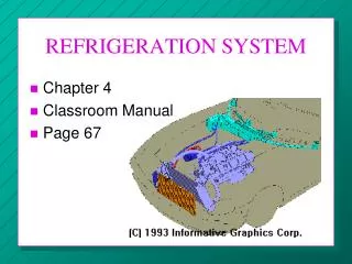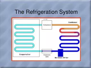
The Refrigeration System
330 likes | 691 Views
The Refrigeration System. PREPARATION. Develop a consistent routine. Use Common Sense Approach Consult Service Manuals Cleanliness Safety. CHECK THESE FIRST. BELT TENSION COMPRESSOR CLUTCH OP COOLING FAN OP BLOWER MOTOR OP AIR FLOW FROM DUCTS REFRIGERANT CHARGE SERVICE VALVES

The Refrigeration System
E N D
Presentation Transcript
PREPARATION • Develop a consistent routine. • Use Common Sense Approach • Consult Service Manuals • Cleanliness • Safety
CHECK THESE FIRST • BELT TENSION • COMPRESSOR CLUTCH OP • COOLING FAN OP • BLOWER MOTOR OP • AIR FLOW FROM DUCTS • REFRIGERANT CHARGE • SERVICE VALVES • LINES, HOSES, CONNECTIONS • AMBIENT AIR TEMP
Refrigerant • A compound used in mechanical refrigeration systems • Used to transfer heat • R-134A used since 1996 • Contains no chlorine • Many older systems can be converted to R-134A • Available in 1lb & 33lb • Must have certification to purchase
Refrigerant Oil • Lubricates compressor & TXV • Mineral oil in R12 systems • Polyalkylene Glycol (PAG) oil in R134A systems, blue color (water based) • Must maintain specific amount in system • Never reuse old oil, add fresh oil
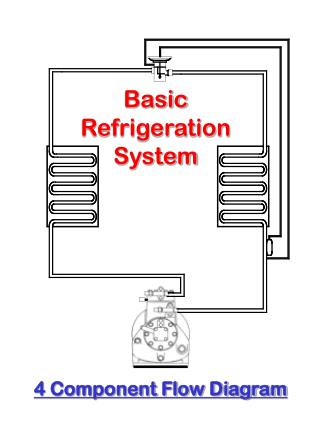
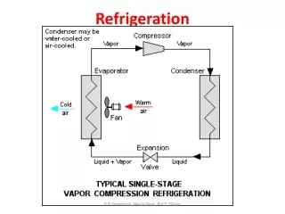
Temp & Pressure Relationship • To keep Evap just above freezing (icing) • Refrigerant temps & pressures closely related • Low side temp/ Evap • High side temp/condenser
Temperature-Pressure Relationship Chart Temp R134A Temp R134A Temp R134a 0 6.5 55 51.2 110 146.3 5 9.1 60 57.4 115 158.4 10 12 65 64 120 171.1 15 15.1 70 71.1 125 184.5 20 18.4 75 78.6 130 198.7 25 22.1 80 86.7 135 213.5 30 25.3 85 95 140 229.2 35 30.4 90 104.3 145 245.6 40 35 95 113.9 150 262.8 45 40 100 124.1 50 45.4 105 134.9
A/C temperature testing • True test of systems ability to cool • Is normally measured at center outlet • Procedure: • Run system @ med blower, engine @ 1500 rpm • Engine warm let idle, blower low • Measure temp @ center vent • Should be 20 degrees reduction over incoming air
A/C pressure testing MUST WEAR EYE PROTECTION!!! • Manifold gauge set • Low side gauge • A compound gauge reads both pressure & vacuum • low side, blue hose
A/C pressure testing • High side gauge • Measures pressure only • High side, red hose
A/C pressure testing • Yellow center hose • Hooked to service equipment • Two hand valves control flow. • Must be closed while testing • All hoses are anti-blowback
Test ports • Quick connect • Covered by protective caps, reduces slow leakage • Special schrader valve
Pressures - low side • Reflects evap temp • R12 systems run 25-35 psi • R134a systems run 20-25psi
Pressures - high side • Reflects condenser temp • All systems vary based on ambient temps • R12 will typically run 150-250 psi • R134a systems up to 300 psi
NORMAL OPERATION #1 • Low-side gauge: Normal pressure • CFC-12 32-33 psig HFC-134a 30-31 psig • High Side Gauge: Normal Pressure CFC-12 185-190 psig HFC-134a 204-210 psig
INSUFFICIENT COOLING #2 • Low side Gauge: Low Pressure CFC-12 15 psig HFC-134a 12 psig • High Side Gauge: Normal Pressure CFC-12 190 psig HFC-134a 208 psig • Possible Causes: Thermostat (icing) Low side restriction Moisture in system
INSUFFICIENT OR NO COOLING #3 • Low Side Gauge: Low or Very low Pressure • CFC-12: 18 psig • HFC-134a : 15 psig • High Side Gauge: Low Pressure • CFC-12: 130-135 psig • HFC-134a: 139-144 psig • Possible causes: Clogged TXV inlet screen, bad valve, Moisture in system
INSUFFICIENT OR NO COOLING #4 • Low side gauge: Low Pressure • CFC-12: 22 psig • HFC-134a: 20 psig • High side gauge: High to extremely High • CFC-12: 250 psig • HFC-134a 281 psig • Causes: Restriction in High Side • Temperature change present at restriction
INSUFFICIENT OR NO COOLING #5 • Low side: High Pressure • CFC-12: 44 psig • HFC-134a: 43 psig • High side: Low Pressure • CFC-12: 140 psig • HFC-134a: 150 psig • Causes: Bad Clutch, Bad compressor • (compressor not turning normally mech... or electrical)
INSUFFICIENT COOLING #6 • Low Side: High Pressure • CFC-12: 40 psig • HFC-1334a 38 psig • High Side: Normal Pressure • CFC-12: 170 psig • HFC-134a: 184 psig • Causes: Expansion Valve stuck open
INSUFFICIENT OR NO COOLING #7 • Low Side: High Pressure • CFC-12: 42 psig • HFC-134a: 37 psig • High Side: High to extremely High • CFC-12: 235 psig • HFC-134a: 263 psig • Causes: Air in system, Overcharge, overcharge of oil, Clogged condenser, Non op Fans, Engine overheating, Incorrect or contaminated refrigerant