Download
1 / 22
480 likes | 3.16k Views
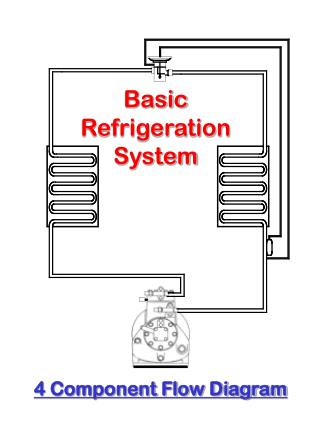
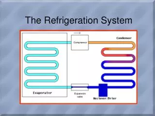
Adsorption Refrigeration System. INTRODUCTION. Adsorption refrigeration system uses adsorbent beds to adsorb and desorb a refrigerant to obtain cooling effect. Adsorption systems mainly use a natural working fluid which have zero ozone depletion potential.

E N D
INTRODUCTION • Adsorption refrigeration system uses adsorbent beds to adsorb and desorb a refrigerant to obtain cooling effect. • Adsorption systems mainly use a natural working fluid which have zero ozone depletion potential. • However, the adsorption cooling machines still have some disadvantages that hinder their wide application. • Inventors propose technologies to improve adsorption system and make it become a realistic alternative. • An assessment is made about current development of adsorption refrigeration technologies.
Disadvantages ofOne Bed adsorption system • Intermittent cooling effect • Low Coefficient of Performance (COP) • Long Cycle Time • Low Specific Cooling Power (SCP)
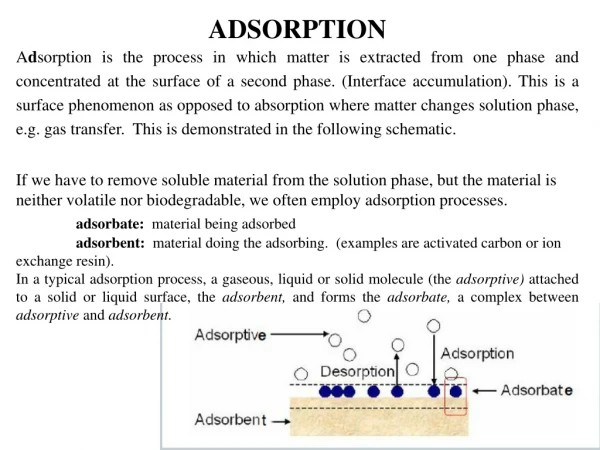
SILICA GEL/WATER ADSORPTION CHILLER INTEGRATEDIN SOLAR COOLING SYSTEM by Dr. Uli Jakob in 2008 • Step 1: Desorption – Drying of the adsorbent • The adsorbent is dried by heat input. Water vapour is set free, flows in the condenser and is liquefied there under heat emission. When the material is dry, the heat input in the adsorber is stopped and the upper check valve closes.
SILICA GEL/WATER ADSORPTION CHILLER INTEGRATEDIN SOLAR COOLING SYSTEM by Dr. Uli Jakob in 2008 • Step 2: Adsorption – • water vapour is adsorbed at the surface of the adsorbent. After a cool down phase the reverse reaction and the evaporation of the liquid refrigerant starts. The lower check valve to the evaporator opens and the dry adsorbent aspirates water vapour. In the evaporator, water evaporates and generates cold.
SILICA GEL/WATER ADSORPTION CHILLER INTEGRATEDIN SOLAR COOLING SYSTEM by Dr. Uli Jakob in 2008 • Step 3: Return of condensate • In a final step, the liquid condensate is returned to the evaporator and the circuit is closed.
Technical data ACS 08 Cooling Capacity 7.5 kW Thermal COP 0.56 Electricity Consumption 9 W Chilled Water Circuit 18/15 °C at 2.0 m³/h Heat Rejection Circuit 27/32 °C at 3.7 m³/h Heat Supply Circuit 72/67 °C at 1.6 m³/h
A Hybrid Solar powered water Heater and Refrigerator by R.Z. Wang in 2000
The working principle is just a combination of a solar water heater and adsorption refrigeration. • Heating of the water tank is started in the morning through vacuum tube type solar collector. With the increasing of the water temperature, the temperature in the adsorbent bed rises. • When the adsorbent temperature rises up desorption of the water vapour is get started from the bed at constant pressure. The desorbed vapor is condensed in the condenser and collected in the receiver. • The liquid flows to the evaporator via an flow rate regulating valve. • A maximum temperature of 80–100°C could be achieved at the end of the process • hot water in the tank could be drained out and moved into another tank thus hot water can be used very flexibly. • With the refilling of the water tank with cold water, the temperature of the adsorbent bed is reduced rapidly and the pressure in the adsorber drops to a value below evaporation pressure . • Evaporation could happen if the connecting valve is open, Refrigeration will continue for the whole night until the next morning.
Rotary thermal regenerative adsorption device by R.E. Critoph in 2001 • A refrigeration/heat-pump system based on a number of simple tubular adsorption modules. • A single module is comprised of a generator and a receiver/condenser/evaporator
Sixteen modules are shown, arranged in a cylindrical shell. All rotate about the central axis. • Air is blown over the tubes, counterflow to their direction of motion and exchanging heat with them. • The carbon is at its coldest, perhaps 50ºC and has maximum concentration at position 1 in fig 2. • As it moves clockwise through the annular duct it is heated by air flowing in the opposite direction. • The carbon is heated it desorbs ammonia which condenses in the receiver section of the module.The module reaches the end of the desorption section it is perhaps at 200º C. • A similar process occurs in the adsorbing section, but with evaporation occurring in the receiver, which cools the airstream passing over it. • All rotate about the central axis typically completing one revolution in 10 min
Heat recovery adsorption refrigeration cycles by R.Z. Wangin 2000
A two beds continuous adsorption refrigeration system with heat recovery is shown in Fig. 1 • When adsorber 1 is cooled and connected to the evaporator to get adsorption refrigeration in the evaporator. • Adsorber 2 is heated and is connected to the condenser to get heating–desorption–condensation. • The condensed refrigerant liquid flows into evaporator via a flow control valve. • The operation phase can be changed, and the go-between will be a short time heat recovery process in which the two pumps drive the thermal fluid in the circuit between two adsorbers. (the connection to the heater and cooler are blocked during this process). • Heat recovery is important to increase the cycle COP.
Solar-Powered Rotary Solid Adsorption Refrigerator by Aiping Zheng Juan Gu in 2004
The low-pressure refrigerant vapor with low temperature from evaporator is introduced to the 3/5 area of the nether part of the rotary adsorbent bed by the gas circulation pump. • it will be adsorbed by the activated carbon fibre, adsorption heat released from the adsorbing course will be taken away by the refrigerant vapor not adsorbed and then enters the solar energy heater. • The refrigerant vapor will be heated by the solar energy heater and its temperature will rise gradually, and it will enter the 2/5 area of the upper part of the rotary adsorbent bed. • The refrigerant will desorbed from the activated carbon fibre when it is heated by the high temperature vapour refrigerant. • the refrigerant is condensed in the condenser by the cooled water. • After being throttled its pressure is reduced, the liquid refrigerant will enters the evaporator. • In the evaporator, the low-pressure refrigerant liquid will adsorb the heat from the cooled medium, and then it will be gasified into refrigerant vapor. • Then the low-pressure low temperature refrigerant vapor will be channeled into the 3/5 area of the under part of the rotary adsorbing bed by the gas pump again and the cycle repeats.
Conclusion • For adsorption refrigeration system, significant achievements have been obtained on the use of various technologies to reduce the complexity of system structure, initial cost, to increase the system operation reliability as well as energy performance. • However, intensive research is still needed to: i) enhance the amount of recovered thermal energy, without adding complexity into the design and operation of system ii) optimize the recovered mass rate to achieve the best effect. • Applied material research could produce new combined material in order to achieve a higher SCP for adsorption refrigeration system.