Download
1 / 45
480 likes | 770 Views
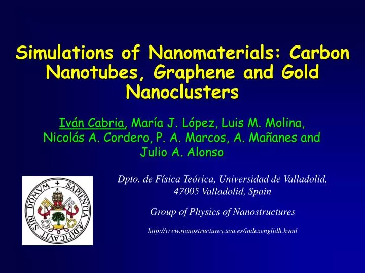
Simulations of Nanomaterials : Carbon Nanotubes , Graphene and Gold Nanoclusters. Iván Cabria , María J. López , Luis M. Molina, Nicolás A. Cordero, P. A. Marcos, A. Mañanes and Julio A. Alonso. Dpto. de Física Teórica, Universidad de Valladolid, 47005 Valladolid, Spain

E N D
Simulations of Nanomaterials: Carbon Nanotubes, Graphene and Gold Nanoclusters IvánCabria,María J. López, Luis M. Molina, Nicolás A. Cordero, P. A. Marcos, A. Mañanes and Julio A. Alonso Dpto. de Física Teórica, Universidad de Valladolid, 47005 Valladolid, Spain Group of Physics of Nanostructures http://www.nanostructures.uva.es/indexenglidh.hyml
Group of Physics of Nanostructrures • University of Valladolid • J. A. Alonso • Cabria • M. J. López • L. M. Molina Other collaborators UAM Mexico:J. Arellano Univ. Guanajuato Mexico: J. Robles DIPC San Sebastian:A. Rubio University of Pennsylvania:L.A. Girifalco, K. Mahadevan, J. Fischer Instituto del Carbón, CSIC, Oviedo: Nacho Paredes, Juan M. Tascón Argonne National Laboratory: Stefan Vajda Group of Simulations of Materials University of Burgos N. A. Cordero P. A. Marcos University of Cantabria A. Mañanes Universidad de Valladolid
Main Lines of Research Related with Nanomaterials and Nanotechnology Can be focused on Materials and/or on Technological Applications Simulations of Properties and Dynamics of Nanomaterials
Main Lines of Research • Carbon Nanotubes • Hydrogen Storage for Hydrogen Cars • New Catalysts made of Gold Nanoclusters
3 nm The discovery of Carbon nanotubes After the C60 fullerene discovered in 1985 CNTs are the new breakthrough of carbon, discovered in 1991 Multiwall Carbon Nanotubes (MWCNTs) were produced by the arc discharge technique • Nested cylinders of Carbon • 4-30 nm in diameter • 1 µm in length Iijima, Nature 354, 56 (1991) Ebbesen, Ajayan, Nature 358, 220 (1992)
Single Wall Carbon nanotubes produced by the arc discharge technique with a metal catalyst cobalt catalyst Bethune et al, Nature 363, 605 (1993) iron catalyst Iijima, Ichihashi, Nature 363, 603 (1993)
Geometrical Construction of SWCNTs by wrapping around a graphene strip in a seamless cylinder Chiral vector: Ch (n,m)uniquely specifies all posssible tube structures Translation vector: T Chiral angle: θ θ = angle ( a1 , Ch ) Hamada et al, Phys Rev Lett 68, 1579 (1992) Saito et al, Appl Phys Lett 60, 2204 (1992)
Types of CNTs structures (5,5) Armchair, θ = 30º (9,0) Zigzag, θ = 0º (10,5) Chiral, 0º <θ< 30º Hamada et al, Phys Rev Lett 68, 1579 (1992) Saito et al, Appl Phys Lett 60, 2204 (1992)
Conducting character of SWCNTs n = m metallic n - m = 3q small gap semiconductor n – m ≠ 3q moderate gap semiconductor Hamada et al, Phys Rev Lett 68, 1579 (1992) Saito et al, Appl Phys Lett 60, 2204 (1992)
Carbon Nanotubes Application of finitenanotubestoSpintronic: electricalcurrentwith spin polarization Separation of nanotubesbyitsmetallicorsemiconductingcharacter Microelectronicsneedsnanotubes of thesameelectroniccharacter Surfactants and nitronium molecular ions are usedtoattackselectively and separatethenanotubes in thebundles
Carbon Nanotubes Chemicalsensorsbasedonnanotubesverysensitivetodifferent gases Funcionalization of nanotubeswithmolecules and/orclusters Changes of theelectricalconductivity of nanotubesduetoextremelysmallamounts of gases adsorbed onthesurface of thenanotubes Applications: environmental, medical, cleanroom control, etc.
Hydrogen Economy - Hydrogen could be an alternative to conventional fossil-fuel sources of energy - Hydrogen is abundant and non contaminant - Hydrogen is NOT a primary source of energy but an energy vector Three Aspects of an Economy based on Hydrogen • Production • Hydrogen Storage • Use: Fuel Cell
Production Hydrogen Economy • Natural Gas: 50 % Production, most common • Water electrolysis: for cheap electricity • Biomass, pirolysis, photobiological processes (bacteria) Electrolysis of water
Hydrogen Economy Production: Prices 1 Kg hydrogen contains the same energy than 4.02 L of gasoline 1 Kg hydrogen occupies 1/0.000089 =11200 L at normal conditions http://www.nanostructures.uva.es/~cabria/hydrogeneconomyandothers.html
Storage Hydrogen Economy • Onboard (cars) and in situ (buildings) storage • Storage methods • LiquidHydrogen • CompressedHydrogen • Stored in a solid
Hydrogen Fuel Cell Cars Hydrogen Car: Electric Car powered by a Hydrogen Fuel Cell instead of batteries Fuel Cell Electric Vehicle in California
Hydrogen Fuel Cell Cars Technological goal: Hydrogen cars equivalent to Fossil Fuel Cars Bottlenecks: fuel cell efficiency and onboard storage Onboard hydrogen storage targets for 2010: 6 weight % of hydrogen 0.045 Kg H2/L at room temperature and moderate pressures, 40-100 atms
Hydrogen Fuel Cell Cars Types of Hydrogen Storage: gas, liquid and solid Mechanisms of Solid Hydrogen Storage: physisorption, chemisorption and chemical reactions Materials that store by physisorption: nanotubes, nanoporous carbons (CDCs, ACs, GNFs, etc.), porous materials such as MOFs, COFs, porous polymers, etc., and metal-doped carbons
Hydrogen Fuel Cell Cars Electric Cars powered by Hydrogen Fuel Cells instead of batteries Compressed hydrogen 100-200 km of autonomy vs 500 km of gasoline cars About 2.5 times more expensive than gasoline cars Hydrogen at 350 bars in Japan, at 700 bars in Europe No room for luggage: Tank with 110 H2 liters at 350 bars 110 CV vs 200-300 CV of gasoline Norway, Fall 2006: First European public hydrogen station
Hydrogen Onboard Storage One of the main Hydrogen economy challenges Hydrogen Storage is one of the bottlenecks of present technology of Hydrogen Fuel Cell Cars Hydrogen has a high energy density by mass: 120 MJ/kg (LHV) 140 MJ/kg (HHV) (gasoline: 44 MJ/kg) But it has a low energy density by volume: 1.5 MJ/L at 150 bars, 0.01 MJ/L at 1 atm and 300 K, 8.4 MJ/L liquid H2 (gasoline: 35MJ/L) LHV: Lower Heating Value; HHV: Higher Heating Value
Hydrogen Onboard Storage One of the main Hydrogen economy challenges A Storage Capacity of 5-10 kg of hydrogen is needed to provide a range of 480 km for a electric-fuel cell car 60 L of gasoline for 480 km 1 kg H2 = 4.02 L gasoline 15 kg H2 15 kg H2 Fuel cell eficiency = 2-3 5-10 kg H2
Hydrogen Onboard Storage DOE targets for 2010 • Specific energy: 7.2 MJ/kg • Gravimetric capacity: 7.2/120 kg H2/kg = 0.06 kg H2/kg = 6 weight % • Energy density: 5.4 MJ/L • Volumetric capacity: 5.4/120 kg H2/L = 0.045 kg H2/L Reversible Hydrogen Storage Note: energy density of hydrogen is 120 MJ/kg for DOE, the LHV value
Hydrogen Onboard Storage DOE targets for 2010 • Operating temperature: 250 – 320 K • Delivery pressure: 2.5 bars • Refueling rate: 1.5 Kg/min or 7 minutes
Hydrogen Onboard Storage Reference gasoline car • Mass fuel storage system: 74 Kg • Volume fuel storage system: 107 L • 75 L of gasoline or 55.4 Kg of gasoline • 600 Km of autonomy • 75 L gasoline × 35 MJ/L gasoline = 2625 MJ • Specific energy: 2625/74 + Fuel cell eficiency=2-5 7.2 MJ/kg • Energy density: 2625/107 + Fuel cell eficiency=2-5 5.4 MJ/L
? Hydrogen Onboard Storage No current hydrogen storage technology meets the targets
Materials for Hydrogen Onboard Storage • GOAL: Find new materials that fulfill the DOE targets for onboard hydrogen storage • Light Materials Porous Materials • Binding energy of H2 to surface: 0.3-0.4 eV/molecule • Graphene Slitpores, Nanoporous Carbons, Carbide-Derived Carbons • Li doped Graphene Slitpores • Pd doped Graphene Slitpores • Molecular Organic Frameworks, MOFs
Simulation of Slitpores Slitpore of width D: two parallel flat layers at distance D Van der Waals interaction of a molecule with the surface Single Layer Slitpore
Relationship between pore size and shape and storage capacity Models for different pore shapes Two parallel graphene layers: slitpore CNTs: cylidrical pores Fullerenes: spherical pores
Storage capacities from the slitpore model Y. Gogotsi, et al. JACS 127, 16006 (2005) Jordá-Beneyto,et al. Carbon 45,293 (2007) The measured storage capacities can be mimicked through slitpores of a single size or a combination of sizes
Pure Graphene Slitpores • Optimal Slitpore Width: around 6 Å • Volumetric and gravimetric goals ARE REACHED above 10 MPa at 300 K • Volumetric and gravimetric goals are reached at moderate pressures at 77 K and for slitpore widths larger than 5.5 Å
Li H2 H2 Li Concavity and Li doping electronic density redistribution = green:+1, yellow -1, 10- 3e/au3 = dark +2, white -2 10- 4e/au3 Eb = 190-200 meV Eb = 310-330 meV
Metal impurities increase binding energy and hydrogen storage Near Li inside: 0.30 eV/molecule!! JCP 128, 144704 (2008) and JCP 123, 204721 (2003) A binding energy of 0.3-0.4 eV/H2 molecule is required for reversible uptake and release at room TLi et al., JCP 119, 2376-2385 (2003) Burgos, November 6th 2009, Project Meeting
Interaction of H2 with Pd doped Graphene molecular adsorption
Metal Organic Frameworks (MOFs) MOFs: New family of highly porous, crystalline materials • inorganic metal oxide cluster + organic linker High Specific Surface Area, SSA = 2000 – 4700 m2/g High porosity volume = 80% High Specific Pore Volume = 1 cm3/g • Promise for hydrogen storage: • tunable pore size: changing the linker • tunable functionality: changing the metal Yaghi & coworkers, Nature 402 276 (1999)
MOF-5 structure crystalline lattice: fcc forms cubes: corners: OZn4 clusters edges: BDC organic linkers Lattice parameter = 25.65 Å Porosity: two types of pores of 15 Å and 12 Å MOF-5 cube red: Zn blue: O gray: C white: H
MOF-5 adsorption sites Direct determination of the adsorption sites using inelastic neutron diffraction: • Yaghi & coworkers, Science 300, 1127 (2003) 2 sites: one associated with the Zn and one with the BDC linker • Yildirim & Hartman, Phys. Rev. Lett. (2005) 2 more sites are identified around the Zn-oxide cluster Theoretical investigation find three main adsorption sites: • CUP between three Ocore-Zn-O-C-O-Zn hexagons • O3 plane above Zn • Benzene Adsorption around the Zn-oxide cluster should be responsible for the high storage capacity of MOFs
Comparison of MOFs with other nanoporous materials MOFs perform better than Activated Carbons and Carbide Derived Carbons at moderate pressures AC from Linares, CDC from Gogotsi, MOF from Yaghi
New Catalysts made of Gold Nanoclusters Goldis noble metal, chemically inactive Butsmallclusters and nanostructures of goldhavecatalyticproperties They are veryefficientfordifferentchemicalreactions of industrial interest GOAL: Design new catalystsmade of goldnanoparticlesforeachspecificchemicalreaction
New Catalysts made of Gold Nanoclusters Wehaveshowntheselectiveoxidation of propenetoformpropylene oxide, used in theproduction of polyurethane
Model for Aun/Al2O3 Clusters are supportedondifferentsurfaces and environments and thesechangetheircatalyticproperties
Perspectives Bimetallic Au-Ag alloy nanoparticles 1ML of Ag1.83O on top of Au(111) corresponds to the situation of a bimetallic alloy with high Au concentration.
Parallel MD Algorithm applied to Economic Organization of Recycling • - EuropeanDirectiveFebruary 2003: take-back and treatment (recycling) of 4 kg of electronicwaste per inhabitant and year • Organization of thetake-back • Optimization of take-back costs • Molecular dynamics algorithm applied to this economic problem
Parallel MD AlgorithmappliedtoEconomicOrganization of Recycling
Interest of Research The results of our research are useful for new technologies and materials related to important activity sectors of our region such as automotive and clean energies
Acknowledgments - Ministerio de Educación y Cienciade España yFSE, Programa “Ramón y Cajal”, http://www.mec.es/ciencia/jsp/plantilla.jsp?area=cajal&id=11 - Ministerio de Educación y Cienciade España: Programa Nacional de Investigación. Planes Nacionales I+D/I+D+I, MAT2005-06544-C03-01 and MAT2008-06483-C02-01 - Junta de Castilla y León, Programa Gral. de Apoyo a Proyectos de Investigación, VA039A05, VA017A08 and GR23 Thanks for your attention