Download
1 / 71
730 likes | 944 Views
Critical Design Review for Cessna Mustang Electromechanical Backup Altimeter & Airspeed. Presenter Subject Time James Ramsey Mustang Team Introductions 9:00 – 9:10 Cessna Mustang Team Introductions 9:10 – 9:15

E N D
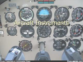
Critical Design ReviewforCessna MustangElectromechanical BackupAltimeter & Airspeed
Presenter Subject Time James Ramsey Mustang Team Introductions 9:00 – 9:10 Cessna Mustang Team Introductions 9:10 – 9:15 James Ramsey Project Overview, Schedule, System Requirements 9:15 – 9:30 Dave Newell Electrical Block Diagram 9:30 – 9:45 Mike Harrison Board Layout 9:45 – 10:00 Bill Hertz DSP Software 10:00 – 10:15 Break 10:15 – 10:30 James Ramsey PIC Software 10:30 – 10:45 Tim Sorenson Software Interface 10:45 – 11:00 Michael Schwader Reliability FEMA 11:00 – 11:15 James Ramsey Reliability MTBF 11:15 – 11:30 Todd White Quality and Certification 11:30 – 11:45 James Ramsey Test 11:45 – 12:00 Lunch 12:00 – 12:30 James Ramsey BIT Discussions 12:30 – 12:45 Brian Nielsen Pilot Interfaces, CDP Assembly, Lighting, Connections 12:45 – 1:00 Brian Nielsen Light/Bit Demo 1:00 – 1:15 James Ramsey Requirements 1:15 – 1:30 James Ramsey Action Items 1:30 – 1:45 Break Out 1:45 – 2:45 Agenda 2
Mustang Team James Ramsey Program Manager Brian Nielsen R&D Engineer Bruce Esposito Quality Engineer Neil Saxon Drafter David Newell Electrical Engineer Todd White Quality/DO 178 Bill Hertz Software Engineer - DSP Tim Sorenson Software Engineer - Interface Mike Harrison PCB Layout Patrick Huyck DER – DO 178B, Level B Joe Ulrich Reliability Engineer Michael Schwader Quality Improvement 3
Project Overview • Product overview • Schedule • System requirements • Risk assessment 4
Cessna CDR - 4/30/04 5 Product OverviewUSB
Cessna CDR - 4/30/04 6 Product OverviewRS232C Interface
Schedule 9
Schedule 10
Requirements • Industry and Regulatory • IR-XXXX-X-MSALT • IR-XXXX-X-MSAIR • Must Have • MH-XXXX-X-MSALT • MH-XXXX-X-MSAIR • Highly Desirable • HD-XXXX-X-MSALT • HD-XXXX-X-MSAIR • Value Added • VA-XXXX-X-MSALT • VA-XXXX-X-MSAIR • XXXX – Number (i.e. 0001) • X - Rev Letter (i.e. B) 11
Hardware - Electrical • Electrical Block Diagram 13
Hardware – Board Layout • Four (4) Boards 18
PWB Design Overview • Cadsoft Eagle Design Software • Valor Computerized Systems (Enterprise 3000) PWB fabrication analysis software • Material: FR4 • Solder Mask (both sides) – LPI • External layer shielding – GND/CGND • .062” nominal board thickness 19
Airspeed I/O PWB DesignPart Number 208914 • (W) 0.750” x (L) 1.625” • (4) four layer design • Components top side only • Interconnect through connectors to DSP and Power Supply 20
Altimeter I/O PWB DesignPart Number 208913 • (W) 0.750” x (L) 1.625” • 6 layer design • Components both sides • Interconnect through connectors to DSP and Power Supply 21
RTC PWB LayoutPart Number 208910 • (W) 0.750” x (L) 1.625” • 4 layer design • Components both sides • Interconnect through connectors to DSP and Power Supply 22
Power Supply PWB LayoutPart Number 208911 • (W) 1.750” x (L) 1.825” • 4 layer design • Components both sides • Interconnect through connectors to RTC, Airspeed I/O or Altimeter I/O 23
DSP PWB LayoutPart Number 208912 • (W) 1.750” x (L) 1.825” • 8 layer design • Components both sides • Interconnect through connectors to RTC, MEMSCAP CCA, Airspeed I/O or Altimeter I/O 24
Software - DSP • Block Diagrams • Data Flow 25
Cessna CDR - 4/30/04 26 DSP Software Block Diagram
Cessna CDR - 4/30/04 27 DSP System Data Flow
Software - PIC • Block Diagrams 28
Cessna CDR - 4/30/04 29 PIC Software Block Diagram
Software - Interface • Maintenance Repair Overhaul (MRO) • Interface • Tasks • OEM 30
Cessna CDR - 4/30/04 31 MRO Interface PC Laptop with interface program. No need to remove instrument. • USB connection on front panel (after removing screw & cover) • Standard USB • Mini-USB on instrument
MRO Tasks • Enable/Disable Trace • View Data Log • View Event Log • Get Time/Date • Display Configuration • Serial Number • Configuration/Part Number • System Info 32
Cessna CDR - 4/30/04 33 OEM InterfaceRS232 Connection • Remove instrument • Proper connector • Have proper OEM software
Advanced Product Quality Planning (APQP) • Define customer needs • Identify characteristics to control to meet customer needs • Verify specification for characteristics are properly set • Verify product can be manufactured • Determine process capability • Identify required controls to produce an “in spec” product • Communicate controls to employees 35
Process Control Development • Design FMEA • Process FMEA • Control Plan 36
Identify functional requirements Determine potential failure mode Measurable condition of product List potential effects of failure Determine severity and class Identify causes Design errors Probability of occurrence Current design controls Probability of an escape Risk potential number (RPN) Design FEMA 37
Determine Potential Failure Mode • Twelve Potential Failure Modes Identified • Inaccurate readings while under IFR at various altitudes and varying degrees of error • Leaks • Inoperative when in Wheels Up mode • Sticks while under IFR • Friction while under IFR • Instrument does not fit in to panel • Instruments lights are out • BIT fails to complete its function • Interface characteristics do not mate properly • Instrument board fails • During WOW instrument fails to communicate with USB 38
Failure Effects, Severity & Class • Identify impact of each potential failure • Given the failure occurred, a severity probability assigned • Numeric value between 1 and 10, 1 being least severe, 10 the most severe • Class assignment • Class I - Catastrophic. May cause death or system loss • Class II - Critical. Severe injury, major property or system damage resulting in mission loss • Class III - Marginal. Minor injury, minor property or system damage resulting in delay or loss of availability or mission degradation • Class IV - Minor. Not serious enough to cause injury, property or system damage. Results in unscheduled maintenance or repair 39
Design Errors & Controls • Potential Causes or Mechanisms of the failure • Probability of occurrence • Numeric value between 1 and 10, 1 being least severe, 10 the most severe. • Current Design Controls that will eliminate the Potential Cause • Prevention Control • Estimate the cause will occur that the Design Control is attempting to prevent 40
Cessna CDR - 4/30/04 41 Design Failure Mode & Effects Analysis (Risk Analysis)Product & Revision Level: Altimeter, Cessna Mustang P/N 162350-1161, Rev N/C
Cessna CDR - 4/30/04 42 Design Failure Mode & Effects Analysis (Risk Analysis)Product & Revision Level: Altimeter, Cessna Mustang P/N 162350-1161, Rev N/C
Reliability • MTBF 43
Reliability Model • Any assembly/component failure considered a failure of the Altimeter/Airspeed Indicator • Reliability model consists of assemblies/components in series • Failure rate calculations based on • Airborne Inhabited Cargo Environment (AIC, AC) at a +30° C ambient temperature 44
Failure Rate Sources • Electronic and electrical • MIL-HDBK-217 predicting principles. • Pressure Sensor Module • Provided by the manufacturer • Both Static and Pitot. • RELEX Reliability Software • Version 7.6 45
Failure Rate Sources • Electronic components • MIL-HDBK-217F, Notice 2, Part Stress Analysis • Used RELEX software • Inputs • Dissipated Power • Rated Voltage • Operating Voltage • Initial Temperature Rise • Worst case operating conditions based on the schematics and component data sheets 46
Failure Rate Sources • Mechanical components • The Handbook of Reliability Prediction Procedures for Mechanical Equipment, document NSWC-98/LE1 • RELEX Software supports this document 47
Failure Rate Analysis • Will be updated to reflect the final design 48
Quality and Certification • Software Lifecycle / Design Control Status • RTCA/DO-178B Level B • Configuration Management • DO-254 Applicability • Document Status • Website • DER 50
Level B Software Verification • Structural Coverage Analysis • Decision Coverage • Requirements-Based Testing • Robustness Testing 51
Lifecycle Development Status • Planning Phase • Preliminary Design • Detail Design • Module Build • System Integration 52
Planning Phase • DO-178B Documents / Status • Plan For Software Aspects of Certification – RELEASED • Software Development Plan – RELEASED • Software Verification Plan – RELEASED • Software Configuration Management Plan – RELEASED • Software Quality Assurance Plan – RELEASED • Program Reviews • Engineering Program Review – COMPLETE • Software Planning Review – COMPLETE • Objective Evidence • Document Review & Transition Criteria Checklists - COMPLETE 53
Preliminary Design Phase • DO-178B Documents / Status • Software Requirement Standards – RELEASED • Software Design Standards – RELEASED • Software Code Standards – RELEASED • Software Requirements Document – RELEASED • Program Reviews • Software Requirements Review – COMPLETE • Preliminary Design Review – COMPLETE • Objective Evidence • Document Review & Transition Criteria Checklists - COMPLETE 54
Detail Design Phase • DO-178B Documents / Status • Software Design Description – RELEASED • Program Reviews • Eight Technical Interchange Meetings – COMPLETE • Critical Design Review – TODAY • Objective Evidence • TIM – Presentation Slides & Action Management System Requirements • CDR – Document Review & Transition Criteria Checklists 55
Module Build & Test Phase • DO-178B Documents / Status • None • Program Reviews • Software Code Review - PLANNED • Weekly Technical Interchange Meetings (TIM) – PLANNED • Low Level Verification • Decision Coverage Verification - PLANNED • Objective Evidence • Transition Criteria Checklist - PLANNED • Detailed Unit Level Test Results - PLANNED 56