Download
1 / 80
820 likes | 1.17k Views
Critical Design Review December 11, 2012. Smart ENergy Delivery ( SEND). Christopher Corey, Josh Crowley, John Fischer, Tim Myers, Neil Severson, Kristine Thompson. SEND Mission. Design and implement smart microgrid energy delivery system

E N D
Critical Design Review December 11, 2012 Smart ENergy Delivery (SEND) Christopher Corey, Josh Crowley, John Fischer, Tim Myers, Neil Severson, Kristine Thompson
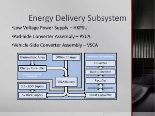
SEND Mission • Design and implement smart microgrid energy delivery system • Combine multiple/varied energy sources in most efficient use of resources possible • Design system to be as grid-independent as possible
Basic System Goals • Detect real time power availability and load demand • Convert sources to single DC bus and deliver required energy to loads • Store energy in battery system for use when resources are unavailable • Monitor load usage and display to user through web interface
Reach Goals • Predictive load profiling • Weather solar resource prediction • System mode control by the user • Load prioritization and control • Add scalability • Allow for multiple source possibilities • System architecture may be followed for higher power applications
Hardware Subsystems • Power electronics • Buck DC-DC converter • Gate Driver • Current Control • Full-wave rectifier • Current and voltage sensing • AC • DC • Battery Charging/Monitoring • Interface with control architecture
DC-DC Switching Converter • Step down PV/rectified grid voltage to DC bus efficiently • Design elements to minimize losses • Conduction • Switching • Size for power level used • Control current draw and power point on PV panel using feedback loop • References provided by central controller
Buck Converter Design • L = = 180μF • C = 3.3 mF • Cutoff above switching frequency • fs = 100kHz • ∆iL = 0.3*IL • Keep out of DCM
Current Programmed Controller • In contrast with a voltage comparator • To set duty cycle • Ideal for implementing a charge controller • Necessary for OPPT • Since current is being measured and compared, most accurate • Not ordinarily stable at duty cycles > 50% • Therefore add a slope compensator
Current Programmed Controller Buffer creates a signal appropriate for the MOSFET Clock sets the output high at the beginning of the period Artificial ramp stabilizes circuit When comparator is triggered output drops low, setting the duty cycle
Current Programmed Controller Clock sets the output high Comparator condition met, output set low Slope compensation and reference current Inductor current
Current Programmed Controller • Choosing a chip to match our requirements: • Large duty cycles • 100kHz frequency • 12V operation • Current sense/ mode control • Good documentation
UC3843 Slope compensator for stability Current Transformer for isolation and efficiency Oscillator Input filter
Gate Driver • However the duty cycle output is 5V • Not sufficient to drive the MOSFET • Vgs = Gate, Source Voltage Minimum 12V
Gate Driver • The gate driver takes the 5V duty cycle and converts it to a signal for the MOSFET • Represented by the buffer on the output
Gate Driver 12V 0V Voltage Limit Dampening Resistor Step down transformer From CPC MOSFET Driver Charge Capacitor Bleed Resistor 12V -12V
Rectifier Full bridge rectifier Smoothing capacitor for DC voltage
Rectifier Converter • Necessary to match the changing battery voltage • Steps down input voltage • Requires current programmed controller and gate driver • Signal from main controller
MSP430 Connections • 3.3V UART • Beaglebone • SPI • AC Current/Voltage Sensing • ADC • DC Current/Voltage Sensing • PWM • Current Reference
ADE7753 Optoisolation • ADE7753 5V TTL Logic • MSP430 3.3v • ADE7753 connected to high voltages, such as 120V RMS on the grid connection.
MSP430 Drivers • To minimize code refactoring, we isolated hardware dependent code in driver software modules. • Minimized changes when transitioning from MSP430f636 to MSP430f6333
Software State • Software state determined by battery state of charge. • State 0 – Initialization • State 1 – Low Battery • State 2 – Sufficient Battery • State 3 – Maximum Battery
BeagleBone • Python • Serial Interface • Weather Forecasting • Database Connection (Write) • Mysql • Single Database Multiple Tables • Lighttpd • Single site send.int.colorado.edu • PHP • Database Connection (Read)
Progress in Software Development • Software Drivers developed and tested on the MSP430 F6736 series • Serial • Analog to Digital Conversion • Load Monitoring Prototype • Open-Loop Toroid • User Interface • Minimizing use of the BeagleBone
MSP430 Status • Testing and Prototyping done on F6736 series • Sampling Times • ¼ second per 1000 samples • Considering a move to F433x series given an increase in hardware ADCs • F433x series provides 12 ADCs at up to 12bit precision • Drivers would need to be ported
Load Monitoring Prototype • Resistive loads should be more accurate indicating incorrect calibration constant • Non-Linear Differences when adding/removing loads • Mitigate using Energy Sense IC with <0.1% error
User Interface • Energy Data • Real-time updating graphs of load usage • Weather Prediction • Solar radiance prediction using cloud cover data from weatherunderground.com • Javascript + Highcharts • Fast rendering • PHP Development • Future of the User Interface