Download
1 / 17
170 likes | 347 Views
iSHELL Design Review Cryostat & Optics Bench. Dan Kokubun 9/11/2013. Overview. Overview. Estimated Weight: 1040 lbs CG: within 2” of optical axis. Helium lines run eastward Hall Effect box placement TBD. Overview. Aladin. Cal Box. Aladin Controller. LN Can. Rotator Mechanism.

E N D
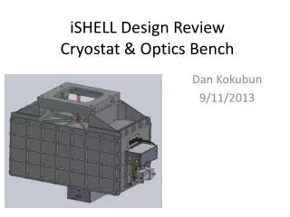
iSHELL Design ReviewCryostat & Optics Bench Dan Kokubun 9/11/2013
Overview • Estimated Weight: 1040 lbs • CG: within 2” of optical axis • Helium lines run eastward • Hall Effect box placement TBD
Overview Aladin Cal Box Aladin Controller LN Can Rotator Mechanism
Overview Order Sorting Mechanism IG Changer *upgrade Cal Box H2RG Controller X Disperser Mechanism H2RG
Cryostat - Housing • Welded Structure • Parts milled from billet • Inserts for Truss mounts pressed in place
Cryostat – Radiation Shield • Eight G-10 Mount tabs (1.9W heat load) • Pre-polished panels • Access panels for wire harness installation • Slots for truss clearance during installation • Covers for access to truss mount bolts
Optics Bench Photon Shield Spectrometer LN Can Bench Bus Bar Photon Shield Foreoptics
Optics Bench – Wire Routing Filter Wheel Rotator • All wires in covered channels • Motor power and heater wires routed together • Hall effect sensors and temperature sensors routed together • Light tight bulkhead connectors Foreoptics Slit Wheel Dekker Mech OS Mech IG Mech Filter Wheel Rotator Spectrograph X Disperser Mech
Optics Bench – Connectors • External access to wire harnesses • Hermetic connectors epoxied to a single plate • Radiation shield access panel Aladin Temp Sens Hall Effect Sens
Optics Bench – Photon Shield • Welded Pan (3mm thk) • Machined Flange • Epoxied joint • Painted inside, polished outside • Qty 32 of #6 screws (4” spacing)
Thermal Design – Hybrid Overview CCC First Stage Cooled Radiation Shielde LN Cooled Bench CCC Second Stage Cooled Aladin and H2RG
Thermal Design – LN Can • LN Can – milled from billet and welded • Cooling Bus Bar mouned with G-10 tabs • Bus Bar Feedthruepoxied to G-10 disk
Cold Stop Alignment Requirement Requirement: To achieve an absolute flux calibration of 1%, the cold stop and telescope exit pupil need to remain co-aligned to within 1% of their diameters both while observing the object, and while performing the flux standard star observations. – Instrument Top Level Specification • Flow Down: • +/- 2.4 mm image movement at the secondary • 1% of Secondary Diameter • Secondary Diameter is 243.84mm • Secondary vertex to Instrument mounting face distance is 8632.84mm • +/-0.016 deg max angular deflection (total budget)
FEA – Displacements • Approximate Results • Three Truss: .015 deg • Four Truss: .005 deg • 4W thermal load
Assembly • Install radiation shield in cryostat • Install bench with trusses • Install RS truss covers • Install wire harnesses and RS access panels • Install photon shields • Install remainder of radiation shield mount tabs (2 per side) • Install radiation shield panels • Install cryostat covers
Notes from Reviewers • WS: Use 1/32 tabs with G10 washers for the bus bar mounts • WS: Use Bellville washers under the cold strap screws • WS: Use t&g on the bus bar feed thru flanges • Weight Issue: • SpeX is 1100 lbs • Cshell is 300 lbs • Consider weight reduction possibilities for iSHELL\ • WS: Reuse SpeX handling equipment if possible • RC: Find out if the cryostat vendor will do post weld stress relief • WS: Make sure the truss mounts are correctly positioned post welding • DW: The radiation shield has over constrained tabs. • ??: Add captive screws on the photon shields • JR: Add a key on the wiring slide (what is blue and what is red) • WS: Epoxy needs to be painted where light leaks are an issue • EW: Use separate holes in the radiation shield for the Aladdin and the other wiring • Multiple: provide more space for wire harness service loops under the connector plates. Suggest making a top hat out of the connector plate. • RC: Use #6-40 screws on the photon shield if larger screws cannot be used. • Don’t forget to include temperature sensors for engineering evaluation • Need to resolve epoxy vs. welding approach for the photon shields • JR: Need a getter on the cold finger • JR: Need to fine tune the A/L for the bus bars and flexible straps • AT: Review the FEA with Vern and Morgan • AT: Need to develop an assembly plan and handling equipment • Need to make the cryostat bigger. Allow for ½” clearance between the radiation shield and the cryostat/bench. DK: Will also consider making the photon shield flanges wider to accommodate larger screws. • AT: have followup detailed design reviews in two parts • 1. Discussion of assembly and optical alignment • 2. Final review at the 100% completion mark • JR: Add the Slit viewer assembly in the applicable slides