Download
1 / 33
330 likes | 453 Views
This document outlines the mechanical design considerations for the Adaptive Optics Module, including weight and balance, packaging, access to components, thermal management, and structural aspects. It covers issues such as vibrations, reflections, and performance optimization. The preliminary design review includes analyses like finite element analysis, seismic stress analysis, and alignment procedures. Sensitivity analysis, error budget charts, and components for closed-loop control are detailed for final alignment and operational phases.

E N D
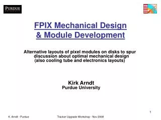
Adaptive Optics Module Mechanical Design Eric James
Major Design Issues • Packaging • Weight and balance • Volume • Access to components • Structural • ISS interface • Flexure/vibrations • Thermal expansion • Performance • Minimize surfaces • Minimize reflection angles MCAO Preliminary Design Review
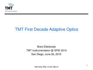
8 meter Primary Mirror AOM Location Multi-conjugate Adaptive Optics Cassegrain Rotator Instrument support structure AO Module MCAO Preliminary Design Review
Electronics Bay Optics Bay Electronics Bay MCAO Preliminary Design Review
Optical Paths Science path Beam splitters LGS focus NGS focus LGS path NGS path Science focus MCAO Preliminary Design Review
Optical Bench MCAO Preliminary Design Review
Bench Support MCAO Preliminary Design Review
Electronics Enclosures 9U 19”rack mount chasses (12 total) MCAO Preliminary Design Review
Electronics Bay Open MCAO Preliminary Design Review
Thermal Management Heat exchanger 100 mm foam insulation at optics bay Air flow 50 mm foam insulation elsewhere Calculated heat loss to dome: 35 –85 Watts MCAO Preliminary Design Review
Finite Element Analysis • Static (Gravity Induced) Flexure Analysis • Telescope at zenith • Zenith angle = 45º • Zenith angle = 60º • Dynamic (Vibration Induced) Flexure Analysis • Natural frequency • Vibration Amplitude • Seismic (Earthquake Induced) Stress Analysis MCAO Preliminary Design Review
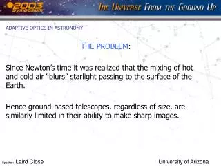
Static Analysis at Zenith Telescope at Zenith: Maximum deflection ~50 mm Gravity MCAO Preliminary Design Review
Static Analysis at 60º from Zenith Telescope at 60º from Zenith: Maximum deflection ~200 mm Gravity MCAO Preliminary Design Review
Dynamic Analysis Dynamic Analysis Mode 1: “fishtailing” motion Lowest natural frequency: 39 Hz MCAO Preliminary Design Review
Seismic Analysis Seismic Analysis Maximum Stress: ~ 8 x 10⁶ Pascals MCAO Preliminary Design Review
Alignment • Initial Alignment (acquire image) • Align elements within major components to datum surface. • Done by vendor at vendor facility. • Align components and single elements to the optical bench. • Align optical bench to the telescope. • Done by Gemini on the telescope at Gemini south. • Final Alignment (optimize image) • Wave front analysis using source simulators and wave front sensors. • Image analysis using stars and science detector. MCAO Preliminary Design Review
AO Module Sensitivity Analysis • Optical fabrication and alignment sensitivities computed • Modeling accounts for partial compensation of errors by the AO control loops • Initial alignment in the lab • Flexure/thermal errors during closed-loop operation • Sensitivities computed for • Higher order wave front errors (science, NGS, LGS paths) • Pupil alignment/distortion (science, LGS paths) • Boresight (tip/tilt) errors (science, LGS paths) • DM adjustments to compensate errors MCAO Preliminary Design Review
Error Budget chart MCAO Preliminary Design Review
Sensors and compensators for final alignment in the lab Distortion map Astronomer Mean tip/tilt and higher order correction (3 x 35 Zernikes) DMs Diagnostic WFS Source simulator Science Instrument NGS WFS LGS WFS Tip/tilt/focus adjustment • Tip/tilt/focus adjustments • Pupil alignment Non-common path calibration Influence function measurements MCAO Preliminary Design Review
Sensors and compensators for closed-loop AO • M2 focus • Telescope pointing On-axis Tip/tilt/focus Telescope DMs OIWFS 3 by 35 Zernikes • LGS WFS focus • NGS WFS boresight Least-squares fit NGS WFS 3 x tip/tilt Pupil mirror LGS WFS 5 by 35 Zernikes (tilt removed) 5 x tip/tilt LGS pointing MCAO Preliminary Design Review
Wave front error budget results Red numbers indicate the value is over budget or at least of some concern MCAO Preliminary Design Review
Error Budget points of interest • Most areas meet goals. All goals are met at the zenith position. • Flexure at 45º and 60º are about 50% over the goals. This suggests special design effort at a few areas. • Science path tip/tilt errors must be carefully calibrated out. • Within goals for: • LGS pupil displacement (input to simulations) • LGS WFS boresight errors (input to simulations) • LGS RMS pupil distortion (input to simulations) • RMS wave front errors in LGS and NGS paths • DM adjustments MCAO Preliminary Design Review
Active Components • Source simulators • Science ADC • DM0 aperture stop • Beam splitter changer • Diagnostic wave front sensor • Shutters • NGS wave front sensor • NGS ADC • LGS zoom corrector • LGS wave front sensor MCAO Preliminary Design Review
LGS wave front sensor Active lenses Commercial tip/tilt mirrors CCD detectors 5 beam paths – 2 omitted for clarity MCAO Preliminary Design Review
NGS Wave front sensor Probe arms NGS path NGS path X-Z translation stages MCAO Preliminary Design Review
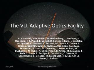
Diagnostic WFS/Source simulators • LGS Source • 5-star constellation • LEDs at ~.589 microns • NGS Source • 5x5 array of 4 micron diameter fiber sources • 8 200 micron diameter sources at ~ 1 arc minute radius NGS Source LGS Source CCD detector Video camera (not shown) Diagnostic WFS MCAO Preliminary Design Review
LGS Zoom Corrector Moving elements LGS wave front sensor Fixed elements MCAO Preliminary Design Review
Beam splitter changer Rotation to change beam splitters Science path To Science instrument Science path From DMs Science ADC LGS/NGS path MCAO Preliminary Design Review
Misc. Active components • Science ADC • Counter-rotating prisms • Retractable • Calcium fluoride and silica prisms • NGS ADC • Counter-rotating prisms • Flint and crown prisms • Shutters • Baseline same as Altair • Aperture stop • Normally retracted, used only with source simulator to overfill DM0 for flattening. MCAO Preliminary Design Review
Mass and Center of Gravity Goal center of mass 13 mm 1060 mm 1200 mm 900kg 970kg (estimated) MCAO Preliminary Design Review
Procurement strategy -5 work packages: • AO Bench (including enclosures and most electronics) • Deformable mirrors • Diagnostic WFS & source simulators • LGS wave front sensor • NGS wave front sensor MCAO Preliminary Design Review
Procurement Strategy –Acceptance testing & Integration DWFS/ Sources NGS WFS AO Bench DMs LGS WFS Vendor facilities: Pre-ship tests Hilo: Acceptance tests, integration, & closed-loop AO Cerro Pachon: reassembly, realignment, & commissioning MCAO Preliminary Design Review
Thursday, 5/24 0800 Welcome 0805 Project overview 0830 Science case 0930 Break 0945 System overview System modeling 1100 AO Module optics 1145 Lunch 1245 AO Module mechanics 1340 AO Module electronics 1400 Break 1415 Beam Transfer Optics 1510 Laser Launch Telescope Closed committee session 1800 Adjourn PDR Agenda MCAO Preliminary Design Review