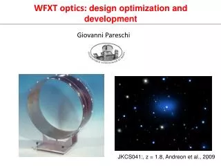
BSRT Optics Design
BSRT Optics Design. BI Days 24 th November 2011 Aurélie Rabiller BE-BI-PM. Summary. BSRT Overview Light sources, optics Present system: spherical mirrors Advantages Limitations and encountered problems New system under study: lenses Advantages Limitations

BSRT Optics Design
E N D
Presentation Transcript
BSRTOptics Design BI Days 24th November 2011 Aurélie Rabiller BE-BI-PM
Summary • BSRT Overview • Light sources, optics • Present system: spherical mirrors • Advantages • Limitations and encountered problems • New system under study: lenses • Advantages • Limitations • Abort gap monitor line modification BI Days 2011 - BSRT Optics Design
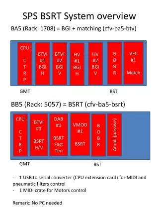
BSRT Layout BSRT: Beam Synchrotron Radiation Telescope Beam transverse profile monitoring with synchrotron light Optical line shared with: • Abort gap monitor • Longitudinal density monitor Extraction mirror Proton/Ion beam Slow camera (BSRTS) Optical delay line Fast camera (BSRTF) 60 % Motorized mirror Abort Gap Monitor (AGM) 40 % Neutral filters 10 % Color filters 90 % Long. Density Monitor (LDM) • Two systems in LHC • One system in lab 10 % 90 % BI Days 2011 - BSRT Optics Design
Synchrotron light sources Light sources: • Dipole (edge to center): Visible light from 1.3 to 7 TeV • Undulatorespecially design to create visible light from 450 GeV to 1.3 TeV Dipole D3 Undulator Extraction mirror in beam pipe Syncro light from und. Syncro light from dipole Proton/ion beam 27.6m 1.6m 0.7m 0m 6.3m BI Days 2011 - BSRT Optics Design
Imaging system • first focusing element: f= 4 - 5m • inverted intermediate image with mag = 0.15 - 0.2 • second focusing element: f= 0.3 - 0.8m • final image with mag = 0.3 - 0.6 Object Intermediate image Final image 1-2m 0.5-1m 28-32m 4-5m The system is limited by diffraction: the smaller the wavelength, the smaller the aberration => use of bandpass filters BI Days 2011 - BSRT Optics Design
Some pictures BI Days 2011 - BSRT Optics Design
Present design: spherical mirrors • Motorized 8 mirrors “trombone” to follow light source • Spherical mirror f=4000mm (F1) • Spherical mirror f=750mm (F2) • Cameras • Total magnification: 0.3 (0.14 @ intermediate image plane) F1 90%R Window F2 Entrance mirror 1 2 3 4 BI Days 2011 - BSRT Optics Design
Present design: Advantages Object Plane Image Plane No chromatic aberrationsPSF ≈ 18um for all wavelength’s 100 um 100 um 1mm 450nm: PSF = 18um 350nm: PSF = 18um 100 um 100 um Image of 1mm grid object 600nm: PSF = 18um 550nm: PSF = 18um BI Days 2011 - BSRT Optics Design
Present design: Limitations • Transmission: 8 mirrors trombone = 30% intensity loss (even more @ 400nm) • Aperture: only 26% efficiency @ 450GeV for one pass trombone, even less with two pass trombone • Alignment of the trombone really difficult and needs frequent retuning => efficiency is even more reduced Less light collected => larger bandpass filter => bigger aberration due to diffraction BI Days 2011 - BSRT Optics Design
Present design: Limitations • Design in reflection • small angles in X plane, back and forth optical path’s really close to each other • Tight space for inserting elements without intercepting the light • Abort Gap coupled to BSRT • steering done with the 1st mirror, in common with BSRT BI Days 2011 - BSRT Optics Design
Present design: Limitations Emittance measurement: At present, PSF is more than 300um and not constant Possible causes: • Diffraction • Vibrations • Alignment changes • Idea: Simplify the optical system : • More reliable alignment • Reduce vibration BI Days 2011 - BSRT Optics Design
New design: Lenses • Lens optimized between 350 and 600nm, f=5000mm (L1) • 2 fold mirrors • Optimized lens f=300mm (L2) on motorized TS to follow light source • Camera • Total magnification: 0.6 (0.21 @ intermediate image plane) • Separate line for abort gap monitor by adding splitter before 1st mirror 1 2 3 4 BI Days 2011 - BSRT Optics Design
New design: Advantages • No more trombone: only 2 mirrors in the system instead of 8 => intensity loss ≈ 10% • Aperture increased: 1st lens closer to entrance mirror => efficiency @ 450 GeV ≈ 42% • Much easier alignment • No more small angles in X plane due to reflection:more room for inserting elements • Abort gap monitor decoupled: in view of future interlock system BI Days 2011 - BSRT Optics Design
New design: Limitations • Chromatic aberrations: lenses for 350 to 600nm region, but not as good as spherical mirrors, PSF ≈30um 100 um 100 um 1mm 450nm: PSF = 13um 350nm: PSF = 25um 100 um 100 um 600nm: PSF = 57um Image of 1mm grid object 550nm: PSF = 25um BI Days 2011 - BSRT Optics Design
New Design for Abort Gap • Beam splitter T=92% above entrance mirror • F=2000mm plano-convex lens • 2 fold mirrors (one motorized) • Camera to check beam presence and alignment BI Days 2011 - BSRT Optics Design
Lab and tunnel test plan BSRT: • Test in lab to validate the system as completely as possible • Magnification, aberrations, transmission, alignment procedure... Abort Gap Monitor: • Test in lab (mostly alignment procedure) • Installation in the tunnel on one side during the shutdown • In addition to the present system BI Days 2011 - BSRT Optics Design
BSRT in LHC SC Undulator Sync. Rad. Monitors D3 Dipole BI Days 2011 - BSRT Optics Design