Download
1 / 31
320 likes | 503 Views
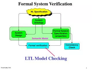
Formal verification in Embedded System design. Dr. Abhik Roychoudhury School of Computing abhik@comp.nus.edu.sg. Safety Critical Systems. Safety Design invariants must always hold in all executions of the system. Critical Violating invariants in any execution can be disastrous .

E N D
Formal verification in Embedded System design Dr. Abhik Roychoudhury School of Computing abhik@comp.nus.edu.sg
Safety Critical Systems • Safety • Design invariants must always hold in allexecutions of the system. • Critical • Violating invariants in any execution can be disastrous. • Examples • Air traffic controller • Automobile parts.
Methodological view point • Inject higher reliability in design life cycle. • Safety critical systems often have a computer component. • This trend is increasing with growth of embedded applications. • What kind of computer systems are they ?
Reactive Systems • Continuously interacts with its environment. • Interaction with env. is asynchronous. • Often, its response to environment needs to obey time constraints. • Often consists of a concurrent composition of processes. • [Harel]
Why study them now ? • Embedded systems • Using a computer component as part of a bigger system becoming pervasive. • Many of them safety-critical • e.g. automobile parts • Difficulty in using Current verif. techniques • Lack of tool support for reliable modeling. • Perceived as intrusive to design process.
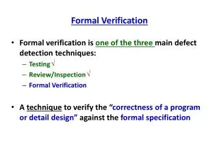
Validation Techniques • In circuit Emulator (ICE) • Logic Analyzer • Model based simulation • Formal verification techniques • Model Checking • Deduction • Combinations of the two
In circuit Emulator (ICE) • Used widely in industry for designs where a microproc. interacts with potpourri of peripherals. • ICE is a dedicated hardware for a particular processor which allows its internals to be read. • Response of processor (to environment) observed by physically replacing chip with ICE.
Logic Analyzer • Used for sampling many signals simultaneously in a complex design. • Can snoop on a bus to observe interactions of a microprocessor with its environment. • ICE and Logic Analyzer do not work when: • Processor, peripherals, bus all integrated in a chip. • System-on-Chip (SoC) – Current industry trend.
Model based simulation • Simulate and observe the behaviors of a system model, rather than the system itself. • Takes validation/debugging higher in the design life-cycle. • Since a model is validated, can take place prior to system integration • Hardware software co-simulation (POLIS) [Earlier lecture]
Model Checking – What ? • Same as model based simulation except that you check all possible behaviors. • Needed for checking critical properties. • Can be used if model has finite states. • Many realistic systems are infinite-state • e.g. real-time systems. • For these systems, extensions of model checking.
Spec. and Impl. • Need a specification language (property to be verified). • Need an implementation language (system to be verified) • Such a language describes reactive system behaviors. • Temporal Logic • Linear - LTL • Branching - CTL • Process Algebra/Calculus • CCS (Milner 1989) • CSP (Hoare) • Finite state automata over infinite inputs.
Model Checking – How ? • Inputs: • finite state concurrent system (implementation as FSM) • Temporal logic formula (specification language) • Output: • True if the specification holds • A counterexample behavior if it does not • Technique: • Implementation FSM is a finite graph. • Unfold and search this finite graph to check all behaviors.
State space explosion • Model checking invariant properties = Reachability computation • Requires visiting reachable set of states (state space). • If a circuit has 100 latches, then maximum 2^100 states. • Visiting and enumerating all these states is inefficient • Space • Time also. • Explicit state model checking quickly runs out of MM. • Need a symbolic representation of the state space.
Symbolic representation • Any state s is an True/false assignment of boolean variables. • X1 = false , X2 = true, X3 = false • This induces a boolean function on these boolean vars. • X1 X2 X3 • Any set of states is also equivalent to a boolean function • ( X1 X2 X3) ( X1 X2 X3) • A canonical representation of this boolean function implicitly encodes set of states (call it Binary Decision Diagram) • X1 X2 • A similar encoding can be obtained for transition relation also. • [McMillan et.al.]
Model Checkers • FormalCheck (Commercialized by Cadence) • Synchronous input language • Based on automata • Symbolic Model Verifier (CMU) • Internal representation : BDD • Mur (Stanford) • Asynchronous interaction via shared variables • Explicit state model checker • SPIN (Bell Labs) • Validation of Protocols/Software
Beyond finite state • Model Checking restricted to finite state systems. • Sources of non-finiteness in reactive emb. Sys. • Data values from unbounded domain - counters • Unbounded data paths • Real Variables, in particular timers • Unbounded number of similar components • Partial specification for some of the system components • How to verify such systems ?
Data Independence • If the control flow of the system is independent of data values • Data values need not blow up the state space. • Infinite number of data values clubbed to a single state. idle In?X Out!X Wait(X)
Data abstraction ……. Receiver Sender Channel Data Delivery y G ( sent = y F (rcvd = y) ) Order preservation x y G ( ( sent = x F sent = y) F ( rcvd = x F rcvd = y) )
Data abstraction • Cannot collapse all data values into a single value. • Choose the abstract data domain based on the property • Data Delivery : { y, y} • Order Preservation : { x, y, {x, y} } • Such data abstractions are routine and can be automated from • System to be verified • Property to be verified (data delivery/ order preservation here) • Abstraction techniques for unbounded data paths • The Channel in this example could be unbounded.
Real time systems • Popular representation : timed automata [Alur et.al.] • Finite state automata • Augmented with finite set of real valued timers • Transitions in the automata occur in zero time. • Time can elapse in states : Delay transitions • State space of a timed automata is infinite. • Finite representation obtained by constructing “timerregions” • Construct region graph where each node is a region. • Model Checking via searching this region graph.
Regions = Constraints x 1 y 1 Corner points : (0,0) (0,1) (1,0) (1,1) Line segments : 0 < x < 1 x = y Open regions : 0 < x < y < 1
Parameterized systems • Infinite family of finite state systems • N process cache coherence protocol • N process distributed algorithm (for mutual exclusion) • A hardware arbiter for resource shared among N processes • Number of processes in the system to be verified is unbounded. • Non-finiteness is not due to data. • Verification is undecidable (no algorithm may exist).
That old trick ! • A network of N similar processes. • Each process has the same finite state automata • { s0, s1, …, sk} • Define a finite vector cnt0, cnt1, …, cntk • Cnt0 = Number of processes in state s0 • Such a vector defines a state of the entire network. • Constraints on cnt0, cnt1, …, cntk now define regions. • If the number of regions in your problem is finite, • Can construct and search finite region graph (Model Checking)
Induction • Example: System : n bit shift register • Initial state : Data fed at left end • property: F out (Data popped at right end) • Cannot construct a uniform proof ( for any n) • Natural to induct on the number of bits. • Induction on process structure (not just number of processes) • Tree networks (e.g. System Buses arranged hierarchically) • Combining limited induction with search (as in Model Checking).
FV for ES – The reality • Is it any different ? • Current verif. Techniques should scale up for ES Hardware. • Embodies hardware/software interaction: often real-time. • Reuse of vendor provided IP blocks • Implementation not known for Intellectual property reasons • No single person/team knows the entire design.
FV for ES – Consequences • Wealth of model checkers (with limited deduction) useful for ES hardware verification • Handle state-of-the-art superscalar processors with • Out-of-order execution • Speculative execution • ES component interaction is fairly detailed, low-level and often specified in hard-to-read manuals. • Real-time verification is not yet a mature technology. • Need to reliably model software-hardware interfaces.
FV for ES - Consequences • A realistic ES design typically consists of: • Number of IP blocks • Connected to one/more system bus via bridges • View an IP block as a hardware subroutine – Need REUSE. • Reuse IP blocks designed by others (and provided by vendors). • Each IP block comes with interface specification • Input and output signals • Some timing diagrams
FV for ES - Techniques • Model Checking (Not the panacea) • Abstraction • Data abstraction on integer counters useful • Routine control abstractions – based on symmetry etc. • A process of gradual refinement – not one shot. • Deduction • Routine inductions – without hypothesis strengthening • Integrate such reasoning with the search • Constraint solving • For real-time feature of ES.
FV for ES - Issues • Synthesizing component interfaces reliably. • Need high level modeling (UML). • Consistency of UML diagrams. • Synthesize executable description from high level models. • Still you might be using other’s components !! • Static verification of unknown components • Assume guarantee reasoning (Deduction) • Extract assumptions/guarantees from interface spec.
FV for ES - Issues • ES software subverts some of the problems of program verification. • Datatypes are often (arrays of) scalar types. • Develop specialized provers (with limited theorem proving) • ES software verification should look at both: • control intensive, reactive applications • Data intensive applications. Reasoning about: • Nested Loops. • Arrays.