Download
1 / 49
490 likes | 608 Views
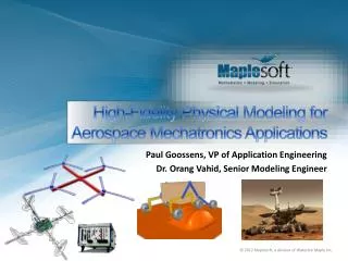
This presentation explores the application of high-fidelity physical modeling in aerospace mechatronics, focusing on recent case studies involving quadrotors and planetary rovers. Key challenges in model-based design and development are examined, along with methods to enhance functionality, quality, and reliability through virtual prototyping. The session highlights the importance of Hardware-in-the-Loop (HIL) testing and validation to minimize errors and development cycles. Attendees will gain insights into emerging challenges such as scalability and complexity in multi-domain modeling.

E N D
High-Fidelity Physical Modeling for Aerospace Mechatronics Applications Paul Goossens, VP of Application Engineering Dr. OrangVahid, Senior Modeling Engineer
Agenda • Introduction • Case Studies: • Quadrotor – Quanser • Planetary Rover – University of Waterloo and Canadian Space Agency • Challenges in Model-based design and development • Maplesoft Engineering Solutions
“Virtual” Prototyping through Model-based Design and Development plays an increasingly key role in system design, commissioning and testing. Increasing adoption of MBD and simulation Reduce prototyping cycles and costs Increase end-user functionality, quality, safety and reliability Deterministic, repeatable testing platform Connection to real components with virtual subsystems through Hardware-in-the-Loop (HIL) Testing is critical to this strategy Validation of subcomponents and/or controllers before integrating into the vehicle reduces errors and costs Validation of model against the real thing improves the whole process, dramatically reducing development cycles and time-to-market in the future Greater demand for greater model fidelity… Physical Model-basedDevelopment
Emerging Challenges... Scalability Capacity Tasks Number of functions (Complexity)
Emerging Challenges... Scalability Multi-domain Modeling Capacity Tasks Number of functions (Complexity) Inputs Driveline Engine/Powertrain Torque/Speed Apply Load??? Chassis/Tire Torque/Speed Outputs
Emerging Challenges... Scalability Multi-domain Modeling Real-time Performance Capacity Tasks Number of functions (Complexity) Inputs Driveline Engine/Powertrain Torque/Speed Apply Load??? Chassis/Tire Torque/Speed Outputs
Qball-X4 Development Paper Concept for Product Rough Feasibility Study Paper Calculations, Low fidelity Simulations Plant Modelin MapleSim
Qball-X4 Development Paper Concept for Product Rough Feasibility Study Paper Calculations, Low fidelity Simulations Plant Modelin MapleSim Export Plant to Simulink Dev RT Controller in QUARC Include Visualization Modify Model Structure, and Fidelity Evaluate Performance Trade various Concepts *Simulink is a registered trademark of The Mathworks, Inc. Quarc is a registered trademark of Quanser Consulting, Inc.
Qball-X4 Development Paper Concept for Product Rough Feasibility Study Paper Calculations, Low fidelity Simulations Plant Modelin MapleSim Export Plant to Simulink Dev RT Controller in QUARC Include Visualization Modify Model Structure, and Fidelity Build Subsystem Prototypes for Technically Risky Subsystems Evaluate Performance Trade various Concepts Parameter Identification *Simulink is a registered trademark of The Mathworks, Inc. Quarc is a registered trademark of Quanser Consulting, Inc.
Qball-X4 Development Paper Concept for Product Rough Feasibility Study Paper Calculations, Low fidelity Simulations Plant Modelin MapleSim Export Plant to Simulink Dev RT Controller in QUARC Include Visualization Modify Model Structure, and Fidelity Build Subsystem Prototypes for Technically Risky Subsystems Evaluate Performance Trade various Concepts Prototype Full System Deploywith Sim Controller Parameter Identification Parameter Identification Deploy Final Product, Controllers Curriculum
Qball-X4 Development Multibody Modeling
Qball-X4 Development Multibody Modeling
Qball-X4 Development Multibody Modeling
Qball-X4 Development Multibody Modeling
Qball-X4 Development Multibody Modeling
Qball-X4 Development Multibody Modeling
Qball-X4 Development Multibody Modeling
Qball-X4 Development Multibody Modeling
Qball-X4 Development MapleSim Model: MultibodyQuadrotor Model + Controller
Qball-X4 Development MapleSim Model: MultibodyQuadrotor Model + Controller
Qball-X4 Development MapleSim Model: MultibodyQuadrotor Model
Qball-X4 Development MOVIE #1
Qball-X4 Development QUARC®/Simulink® Model Generated s-function from the MapleSim plant model *Simulink is a registered trademark of The Mathworks, Inc. Quarc is a registered trademark of Quanser Consulting, Inc.
Qball-X4 Development Flight Test MOVIE #2
Planetary Rovers Rover Modeling: A Multi-disciplinary Approach System Components Rover dynamics Wheels Solar cells Wheel motors Battery Power electronics Heaters Robotic arms, other peripherals Terrain Environment
Steering angle input Angular velocity input Planetary Rovers Six-wheeled Rocker-Bogie Rover Modeling Environment Visualization Environment
Planetary Rovers Rigid Wheel Model
Planetary Rovers Visualization in MapleSim MOVIE #3
Planetary Rovers Rover Kinematics
Planetary Rovers Rover Kinematics Automatic Generation of the Constraint Equations in Maple
Planetary Rovers Rover Kinematics Automatic Generation of the Constraint Equations in Maple -2.*l1x-1.*ySL*cos(xi)*sin(eta)*sin(zeta)+ySR*cos(xi)*sin(eta)*sin(zeta)+zSL*cos(xi)*sin(eta)*cos(zeta)-1.*zSR*cos(xi)*sin(eta)*cos(zeta)-1.*cos(xi)*cos(eta)*xSL+cos(xi)*cos(eta)*xSR-1.*ySL*sin(xi)*cos(zeta)+ySR*sin(xi)*cos(zeta)-1.*zSL*sin(xi)*sin(zeta)+zSR*sin(xi)*sin(zeta) -1.*l1y+sin(xi)*cos(eta)*xSL-1.*sin(xi)*cos(eta)*xSR-1.*ySL*cos(xi)*cos(zeta)+ySR*cos(xi)*cos(zeta)-1.*zSL*cos(xi)*sin(zeta)+zSR*cos(xi)*sin(zeta)+ySL*sin(xi)*sin(eta)*sin(zeta)-1.*ySR*sin(xi)*sin(eta)*sin(zeta)-1.*zSL*sin(xi)*sin(eta)*cos(zeta)+zSR*sin(xi)*sin(eta)*cos(zeta)+l1y*cos(phi)-1.*l1z*sin(phi) -1.*l1z+cos(eta)*sin(zeta)*ySL-1.*cos(eta)*sin(zeta)*ySR-1.*cos(eta)*cos(zeta)*zSL+cos(eta)*cos(zeta)*zSR+l1y*sin(phi)-1.*sin(eta)*xSL+sin(eta)*xSR+l1z*cos(phi) -1.*cos(xi)*cos(eta)*xSL+cos(xi)*cos(eta)*xBL-1.*ySL*cos(xi)*sin(eta)*sin(zeta)-1.*ySL*sin(xi)*cos(zeta)+yBL*cos(xi)*sin(eta)*sin(zeta)+yBL*sin(xi)*cos(zeta)+zSL*cos(xi)*sin(eta)*cos(zeta)-1.*zSL*sin(xi)*sin(zeta)-1.*zBL*cos(xi)*sin(eta)*cos(zeta)+zBL*sin(xi)*sin(zeta)-1.*l3x sin(xi)*cos(eta)*xSL-1.*sin(xi)*cos(eta)*xBL+ySL*sin(xi)*sin(eta)*sin(zeta)-1.*ySL*cos(xi)*cos(zeta)-1.*yBL*sin(xi)*sin(eta)*sin(zeta)+yBL*cos(xi)*cos(zeta)-1.*zSL*sin(xi)*sin(eta)*cos(zeta)-1.*zSL*cos(xi)*sin(zeta)+zBL*sin(xi)*sin(eta)*cos(zeta)+zBL*cos(xi)*sin(zeta)+l3y -1.*sin(eta)*xSL+sin(eta)*xBL+cos(eta)*sin(zeta)*ySL-1.*cos(eta)*sin(zeta)*yBL-1.*cos(eta)*cos(zeta)*zSL+cos(eta)*cos(zeta)*zBL+l3z -1.*cos(xi)*cos(eta)*xSR+cos(xi)*cos(eta)*xBR-1.*ySR*cos(xi)*sin(eta)*sin(zeta)-1.*ySR*sin(xi)*cos(zeta)+yBR*cos(xi)*sin(eta)*sin(zeta)+yBR*sin(xi)*cos(zeta)+zSR*cos(xi)*sin(eta)*cos(zeta)-1.*zSR*sin(xi)*sin(zeta)-1.*zBR*cos(xi)*sin(eta)*cos(zeta)+zBR*sin(xi)*sin(zeta)+l3x xSR*sin(xi)*cos(eta)*cos(phi)-1.*xSR*sin(eta)*sin(phi)-1.*xBR*sin(xi)*cos(eta)*cos(phi)+xBR*sin(eta)*sin(phi)+ySR*cos(phi)*sin(xi)*sin(eta)*sin(zeta)-1.*ySR*cos(phi)*cos(xi)*cos(zeta)+ySR*cos(eta)*sin(zeta)*sin(phi)-1.*yBR*cos(phi)*sin(xi)*sin(eta)*sin(zeta)+yBR*cos(phi)*cos(xi)*cos(zeta)-1.*yBR*cos(eta)*sin(zeta)*sin(phi)-1.*zSR*cos(phi)*sin(xi)*sin(eta)*cos(zeta)-1.*zSR*cos(phi)*cos(xi)*sin(zeta)-1.*zSR*cos(eta)*cos(zeta)*sin(phi)+zBR*cos(phi)*sin(xi)*sin(eta)*cos(zeta)+zBR*cos(phi)*cos(xi)*sin(zeta)+zBR*cos(eta)*cos(zeta)*sin(phi)+l3y -1.*xSR*sin(xi)*cos(eta)*sin(phi)-1.*xSR*sin(eta)*cos(phi)+xBR*sin(xi)*cos(eta)*sin(phi)+xBR*sin(eta)*cos(phi)-1.*ySR*sin(phi)*sin(xi)*sin(eta)*sin(zeta)+ySR*sin(phi)*cos(xi)*cos(zeta)+ySR*cos(eta)*sin(zeta)*cos(phi)+yBR*sin(phi)*sin(xi)*sin(eta)*sin(zeta)-1.*yBR*sin(phi)*cos(xi)*cos(zeta)... 27 Constraint Equations of 36 variables
Planetary Rovers Rover Kinematics Additional Constraints and Forces Differential Joint Steering Wheel/soil forces
Planetary Rovers Rover Kinematics Quasi-static Simulation using MATLAB® MOVIE #4 *Matlab is a registered trademark of The Mathworks, Inc.
Planetary Rovers Rover Path Planning Energy Optimization
Planetary Rovers Rover Component Library Software Component Library Modeling Workspace
Planetary Rovers Hardware Components • Lighting System • Solar Arrays
Planetary Rovers Hardware Components • Battery • Motor • Flywheel • Load simulator • PXI • Sensors
NI® PXI Planetary Rovers HiL Implementation Component Modeling Hardware (Test Bench) Software Lighting System Irradiation Model Solar Panels Solar Panels Charge Controller Battery Battery Motor Inverter Load Simulator LabVIEW™ 2009 Rover Model HiL Graphical User Interface Motor Flywheel
Planetary Rovers HiL Implementation
Planetary Rovers HiL Implementation
Planetary Rovers HiL Implementation – Sample Results Summer Full Load - Pure Hardware vs. Solar Panel, Motor, Load Simulator in the loop Summer Full Load - Pure Hardware vs. Solar Panel in the Loop
What is MapleSim? • MapleSim is a truly unique physical modeling tool: • Built on a foundation of symbolic computation technology • Handles all of the complex mathematics involved in the development of engineering models • Multi-domain systems, plant modeling, control design • Leverages the power of Maple to take advantage of extensive analytical tools • Reduces model development time from months to days while producing high-fidelity, high-performance models
Multi-domain physical modeling Maplesoft Engineering Solutions -dSPACE® -LabVIEW™ -NI® VeriStand™ -MATLAB® & Simulink® -B&R Automation Studio • Driveline Component Library • More Libraries *Simulink and MATLAB are registered trademark of The Mathworks, Inc. All other trademarks are property of their respective owners.
The Symbolic Advantage Best performance Symbolic model simplification Optimized code generation ~10x faster than similar tools Greater insight into system behavior Automatic Equation Generation Advanced analysis Equation-based Model Creation Parameter optimization Enter system equations Sensitivity etc Test/Validate model Multibody kinematics and dynamics Easy component block generation
Hardware in the Loop Simulation Equation andcode generation Controller implementation (and design)Realtime management Embedded controller Data acquisition Plant modelAnalysisController design -dSPACE® -LabVIEW™ -NI® VeriStand™ -MATLAB® & Simulink® -B&R Automation Studio SystemHIL Simulation *Simulink and MATLAB are registered trademark of The Mathworks, Inc. All other trademarks are property of their respective owners.
Key Takeaways... Physical modeling: increasingly important – and increasingly complex – in systems design, testing and integration. Symbolic technology: proven engineering technology that significantly improves model fidelity without sacrificing real-time performance. MapleSim: ideal tool for rapid development of high-fidelity physical models of mechatronics systems to help engineers achieve their design goals.
Thank You!Questions? To stay connected: www.maplesoft.com/subscribe