Chapter 5:Synchronous Sequential Circuits
Chapter 5:Synchronous Sequential Circuits. Logic Design- Review. Logic Circuits. Combinational Circuits. Sequential Circuits. Employ storage elements in addition to logic gates. Outputs are a function of the inputs and the state of the storage elements.


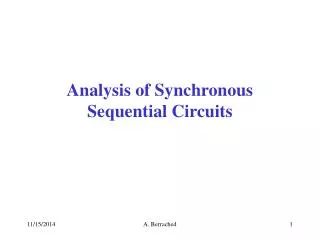
Chapter 5:Synchronous Sequential Circuits
E N D
Presentation Transcript
Logic Design- Review Logic Circuits Combinational Circuits Sequential Circuits • Employ storage elements in addition to logic gates. • Outputs are a function of the inputs and the state of the storage elements. • Output depend on present value of input + past input. • Consists of logic gates whose outputs are determined from the current combination of inputs. • Performs an operation that can be specified by a set of Boolean functions.
Overview Storage Elements and Analysis Introduction to sequential circuits Types of sequential circuits Storage elements Latches Flip-flops Sequential circuit analysis State tables State diagrams
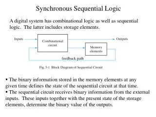
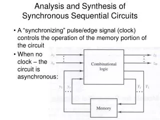
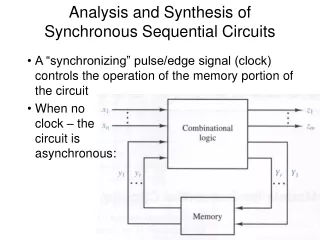
Introduction to Sequential Circuits A Sequential circuit contains: Storage elements:Latches or Flip-Flops Combinatorial Logic: Implements a multiple-output switching function Inputs are signals from the outside. Outputs are signals to the outside. Other inputs, State or Present State, are signals from storage elements. The remaining outputs, Next State are inputs to storage elements. Outputs Inputs Combinational Logic Storage Elements Next State State
Sequential Logic Output functionOutputs = g(Inputs, State) Next state functionNext State = f(Inputs, State) Introduction to Sequential Circuits Outputs Inputs Combina-tional Logic Storage Elements Next State State
Types of Sequential Circuits Depends on the times at which: storage elements observe their inputs, and storage elements change their state Synchronous Behavior defined from knowledge of its signals at discrete instances of time Storage elements observe inputs and can change state only in relation to a timing signal (clock pulses from a clock) Asynchronous Behavior defined from knowledge of inputs at any instant of time and the order in continuous time in which inputs change If clock just regarded as another input, all circuits are asynchronous!
5.3 Storage Elements:Latches Storage elements Maintain a binary state (0 or 1) indefinitely as long as power is delivered to the circuit Switch states (01 or 10) when directed by an input signal Most basic storage element Used mainly to construct Flip-Flops Asynchronous storage circuit Types of latches: SR Latches S`R` Latches D Latches X = X
Basic (NOR) S –R Latch Cross-coupling twoNOR gates gives theS – R Latch: R (reset) Q Q S (set)
Basic (NAND) S –R Latch “Cross-Coupling” two NAND gates gives the S -R Latch: Q S (set) Q R (reset)
Clocked S - R Latch Adding two NANDgates to the basicS - R NAND latchgives the clockedS – R latch: Has a time sequence behavior similar to the basic S-R latch except that the S and R inputs are only observed when the line C is high. C means “control” or “clock”. S Q C S` Q 1 R 1 R`
D Latch(Transparent Latch) Adding an inverterto the S-R Latch,gives the D Latch: Note that there areno “indeterminate”states! D Q C Q Q D Q(t+1) Comment 0 0 0 No change D Q 0 1 1 Set Q 1 0 0 Clear Q Q C 1 1 1 No Change
Graphic Symbols for latches D S Q Q Q Q Q Q C R R S D S’R’ SR
Chapter 5: Sequential Circuits 5.4: Flip-Flops
Flip-Flops The latch timing problem Master-slave flip-flop Edge-triggered flip-flop Other flip-flops - JK flip-flop - T flip-flop
The Latch Timing Problem In a sequential circuit, paths may exist through combinational logic: From one storage element to another From a storage element back to the same storage element The combinational logic between a latch output and a latch input may be as simple as an interconnect For a clocked D-latch, the output Q depends on the input D whenever the clock input C has value 1
The Latch Timing Problem (continued) Consider the following circuit: Suppose that initially Y = 0. As long as C = 1, the value of Y continues to change! The changes are based on the delay present on the loop through the connection from Y back to Y. This behavior is clearly unacceptable. Desired behavior: Y changes only once per clock pulse Y Clock Clock D Q Y Q C
The Latch Timing Problem (continued) A solution to the latch timing problem is to break the closed path from Y to Y within the storage element The commonly-used, path-breaking solutions replace the clocked D-latch with: a master-slave flip-flop an edge-triggered flip-flop
Consists of two clockedD latches in serieswith the clock on the second latch inverted The input is observedby the first latch with C = 1 The output is changed by the second latch with C = 0 The path from input to output is broken by the difference in clocking values (C = 1 and C = 0). The behavior demonstrated by the example with D driven by Y given previously is prevented since the clock must change from 1 to 0 before a change in Y based on D can occur. Master-Slave Flip-Flop D D D Q Q C C C Master Slave Y
State Table 42