Download
1 / 13
130 likes | 305 Views
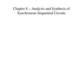
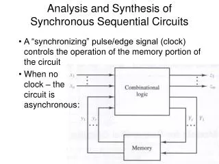
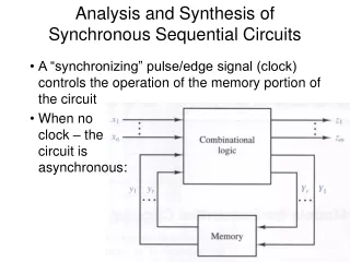
Analysis of Synchronous Sequential Circuits. X 1. X 2. X n. Z 1. Z m. Synchronous Sequential Circuits. Combinational Circuit. Y 1. Flip Flops. Y r. Clock. Synchronous Sequential Circuits. Z i = f i (X 1 , X 2 , …,Xn, Y 1 , Y 2 , …,Yr, )

E N D
Analysis of Synchronous Sequential Circuits A. Berrached
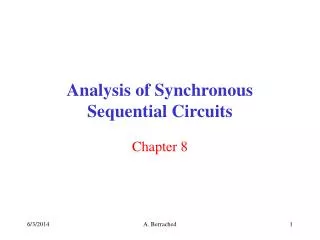
X1 X2 Xn Z1 Zm Synchronous Sequential Circuits Combinational Circuit . .. . .. Y1 Flip Flops . .. . .. Yr Clock A. Berrached
Synchronous Sequential Circuits • Zi = fi(X1, X2, …,Xn, Y1, Y2, …,Yr, ) • Yi = gi(X1, X2, …,Xn, Y1, Y2, …,Yr, ) A. Berrached
Synchronous Sequential Circuits 1. Derive the output equations 2. Derive the F/Fs input equations 3. Derive the next state equations 4. Derive the CKT's State Transition Table State table give a complete description of circuits behavior 5. State diagram 6. Get timing diagrams A. Berrached
Example 1 A. Berrached
Example1 Cont. Step 1: Z = AX' + BX' Step 2: DA = AX + BX DB = A'X Step 3: D F/F characteristic eq. Q(t+1) = D ==> A(t+1) = AX + BX B(t+1) = A'X A. Berrached
Example Cont. Step 4: State Transition Table A. Berrached
Timing Diagram Assume Input Sequence: 00101110 A. Berrached
Example 2 A. Berrached
Example2: Analysis Preliminary: inputs: X outputs: Z State Variables: A & B Note: Moore circuit (1) output equations: Z = AB' (2) Flip Flop Input Equations: JA = B KA = BX' JB = X' KB = AX' + A'X A. Berrached
State Transition Table A. Berrached
Traffic Light Controller • You are to design a traffic light controller to control an intersection. The intersection consists of two streets, one running north-south (called NS) and the other running east-west (called EW). The circuit has to control one traffic lights on the NS street, one traffic light on the EW street. • Each of the traffic signals consists of a red, yellow, and green light. Each of the traffic signals cycles through red, green, yellow, and back to red. When one traffic signal is green or yellow, the other is red. When one traffic light is red, the other is greed or yellow. To simplify the design and shorten the experimentation time, we will set the green, yellow, and red time periods to 4, 1, and 5 seconds, respectively. A. Berrached
Simple Serial Lock • Design a digital lock. Assume only four digits can be entered 0, 1, 2, and 3. • Lock will open when the following sequence of digits is entered, in order: 3, 1, 2, 1. A. Berrached