Download
1 / 32
320 likes | 508 Views
IE 469 Manufacturing Systems 4 69 صنع نظم التصنيع. VII- Flow Manufacturing Systems نظام التصنيع المستمر. 1- Flow System Technology تقنية النظام المستمر. Finished Part. Raw Matl. 1. 2. 3. Buffer. 4. 5. 6. B- Flow system with Buffer. Finished Part. Raw Matl. 1. 2. 3. 4.

E N D
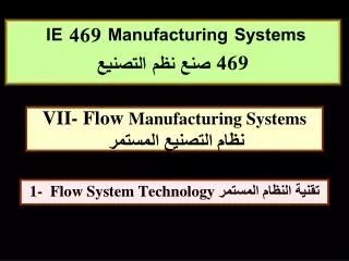
IE 469 Manufacturing Systems 469 صنع نظم التصنيع VII- Flow Manufacturing Systemsنظام التصنيع المستمر 1- Flow System Technology تقنية النظام المستمر
Finished Part Raw Matl. 1 2 3 Buffer 4 5 6 B- Flow system with Buffer Finished Part Raw Matl. 1 2 3 4 5 6 A- Flow system without Buffer 1a- definition تعريف: نظام التصنيع الكبير It is a line of connected number of specialized machines/workstation by suitable handling system based on a sequence of operations to produce a product. هو خط إنتاج مكون من عدد من الماكينات او محطات العمل المتخصصة لأسلوب صناعي (تجميع- تحويل- فحص- تعبئة- فصل--) , وترتبط مع بعضها بمعدات مناولة مناسبة بناءا على تتابع العمليات لإنتاج منتج .
1b- definition تعريف: نظام التصنيع الكبير The line is used for the following cases: يستخدم خط الإنتاج المستمر في حالة • High demand طلب عالي للمنتج • Stable product design تصميم مستقر للمنتج • Long product life cycle دورة عمر طويلة للمنتج • Several sequenced operation تعدد العمليات للإنتاج The line achieve the following ويحقق الخط التالي • Low labour cost خفض في تكلفة العمالة • Low product cost خفض في تكلفة المنتج • Reduce WIP خفض التخزين بين العمليات • High production rate معدلات إنتاج عالية • Specialized & standardized operations التخصص والقياس للعمليات الصناعية • Integrated operations التكامل بين العمليات • Factory layout Area reduction خفض في مساحات المصنع
Preferable for Larger work-pieces Larger number of work stations Buffer Storage to smooth out irregularities نظام بخط In-Line Type Finished Part Raw Matl. 1 2 3 4 5 6 2a- flow line types أنواع نظام خطوط أساليب التصنيع الكبير
2 3 1 Raw Matl. Finished Part 6 4 5 نظام دائري Rotary Type Limited to smaller work- pieces Limited to fewer stations Do not lend to provide buffer storage Low cost equipment Less Factory space floor 2b- flow line types أنواع نظام خطوط أساليب التصنيع الكبير
2c- flow line types أنواع نظام خطوط أساليب التصنيع الكبير
2d- flow line types أنواع نظام خطوط أساليب التصنيع الكبير
2e- flow line types أنواع نظام خطوط أساليب التصنيع الكبير
2f- flow line types أنواع نظام خطوط أساليب التصنيع الكبير
3a- Work-part Transport methods طرق انتقال المشغولة بين المحطات Factors affecting selection of transfer method العوامل المؤثرة في اختيار طريقة الانتقال • The types of operation • The number of stations • The weight and size of the work-parts • including manual stations • Production rate requirement • Balancing the various process time
3b- Work-part Transport methods طرق انتقال المشغولة بين المحطات 1- Continuous Transfer الانتقال المستمرة Work-piece moves continuously. This Requires continuous Work head move; (Beverage bottling Operation-Manual assembly). But not always possible 2- Intermittent/Synchronous Transfer الانتقال المتقطعة/المتزامنة Discontinuous transport motion of Work-piece. Work stations are fixed and work piece moves to proper locations at work head for processing. All parts are moved and processed at same time in synchronous motion.
3c- Work-part Transport methods طرق انتقال المشغولة بين المحطات 3- Asynchronous Transfer الانتقال الغير المتزامنة Work-piece moves independently after processing at current station to next station. Some parts are being moved and other parts are being processed at same time. Greater flexibility is offered for processing time variation and line balance, by allowing In-process storage and parallel stations in the line. But the cycle time is increased.
3d- Work-part Transport methods طرق انتقال المشغولة بين المحطات 4- Pallet Fixture منصات تحميل المشغولات Work-piece is attached to pallet fixture to carry work-piece through sequence of operations. It transfer the work-piece and helps Positioning and locating at the machine.
1- Walking Beam 2- conveyer System 4a- Transfer Mechanismsآليات الانتقال 1- Linear Transfer Mechanisms آليات الانتقال الخطي
4b- Transfer Mechanismsآليات الانتقال معادلة آلية الانتقال الخطي Walking Beam Geometry hs = Lifting Height ds = Distance between work-stations b = Walking beam size (10 hs) Smin = Minimum piston stroke Smax = Maximum piston stroke
1-Rack and Pinion 3-Geneva 4- Cam 2-Ratchet and Pawl 4c- Transfer Mechanismsآليات الانتقال 2- Mechanisms Rotary Transfer آليات الانتقال الدائري
Pin to index driven wheel rd Driver wi wd Qi Driven wheel 4d- Transfer Mechanismsآليات الانتقال معادلة آلية جينيفا MechanismsGeneva
wi rd ri qd qi wd Qi Qd 4e- Transfer Mechanismsآليات الانتقال معادلة آلية جينيفا MechanismsGeneva
wi rd ri qd qi wd Qi Qd 4f- Transfer Mechanismsآليات الانتقال معادلة آلية جينيفا Mechanisms Geneva
ri rd a Qd/2 Qi/2 C d معادلة آلية جينيفا Mechanisms Geneva 4g- Transfer Mechanismsآليات الانتقال
Indexing angle, Distance between drive and index centers, Since the non-drive must correspond to cycle time, the rotation of drive motor can be: Drive angle, Drive diameter, Example for Geneva mechanism مثال لمعادلة آلية جينيفا 4h- Transfer Mechanismsآليات الانتقال Find motor speed, if a rotary system requires three work-station with cycle time of 0.5 min. Assume, the indexer wheel diameter equal to 12 in. In this case, the drive motor rotate every 36 sec. For constant speed motor the ratio of time spend in processing to time spent indexing = 300:60.
Finish Prod. Base Part 1 2 3 4 5 6 نظام بخط In-Line Type 5-1a- Assembly system أنواع نظام خطوط التجميع تتماثل أنواع محطات خط التجميع والانتقال بينها مع خطوط أساليب التصنيع , والاختلاف بينها يكمن في طبيعة العمل وتصمم كل محطة تجميع للقيام بمهمة أو مهام لأساليب تجميعية باتزان الخطوط حيث الأجزاء تقدم للمحطة لعملية التجميع بحيث: • تستقبل المحطة الأجزاء إلى المحطة بواسطة آليات تقديم لإتمام عمليات التجميع • تثبت قاعدة أساسية على منصة تحميل تتحرك بين المحطات ليتم عليه التجميع Assembly line resemble the process line and the difference lie in the nature of work activity as follow. Assembly station is designed according Line Balancing to carry assembly process (s) such that: • parts are fed to each station by feeder mechanisms • A base part is fixed on pallet and transported through the stations to carry assembly operation of parts.
Robot assisted assembly Labor intensive conveyer assembly 5-1b- Assembly system أنواع نظام خطوط التجميع
(B) Final assembly (A) Half cap sub-assembly Gillette safety razor Sequence of Half cap sub-assembly Unload Feed Snap Load Feed Snap 5-1c- Assembly system أنواع نظام خطوط التجميع
3 2 1 4 2 Base Part 1 Finish Prod. 4 3 6 5 نظام دائري Dial Type نظام دائري Carousel Type Base Part 1 Finish Prod. نظام محطة تجميع واحدة Single station assembly 5-1d- Assembly system أنواع نظام خطوط التجميع
5-2a – work transfer system أنظمة الانتقال بين المحطات
1 2 3 4 5-3a- Part feeder to base part انتقال القطع لقاعدة التجميع
Vibratory Bowl Feeder Center-board Bowl Feeder 5-3b- Part feeder to base part انتقال القطع لقاعدة التجميع 1- Hopper: Bulk container for a type of component and initially oriented. 1a- Part feeder: A mechanism that removes the parts from the hopper one a time for delivery.
(a) Selector (b) Orientor Use of light source for part orientation 5-3c- Part feeder to base part انتقال القطع لقاعدة التجميع 2- Selector and Orientor: They establish the proper orientation of the component.
Escapement of riveted shaped parts Placement onto index Table Pick And Place Mechanism (a) (b) 3- Feeder track: It transfers the component from the Hopper and selector to the escapement and location on work-station head. Two types are used: gravity and powered. 4- Escapement and placement device: It removes a component from the track at time intervals that are consistent with the cycle time of the assembly head. 5-3d- Part feeder to base part انتقال القطع لقاعدة التجميع
Feed rate f O O O Lf2 f Delivery Rate Lf1 1- LC 5-3e- Part feeder to base part انتقال القطع لقاعدة التجميع Stop Sensor Start Sensor RC Cycle Rate
Given: Cycle time; TC = 0.2 min, Feed rate: f = 20 components/min, Passing part to feed track: = 0.3, Number of parts in feed track at low level nf1=6, Number of parts in feed track at high level nf2=18. O O • The time taken for the supply parts to from nf1 to nf2 =(nf2 - nf2)/(f -RC ) =(18-6)/(20 x 0.3 – 5)=12 min. 5-3e- Part feeder to base part انتقال القطع لقاعدة التجميع Determine: a) What is the time it will be taken for the supply parts to fromnf2 to nf1 b) What is the time it will be taken for the supply parts to fromnf1 to nf2 Solution: • The time taken for the supply parts to from nf2 to nf1 = (nf2 - nf2)/RC =(18-6) x 0.2 = 2.4 min