Download
1 / 27
270 likes | 420 Views
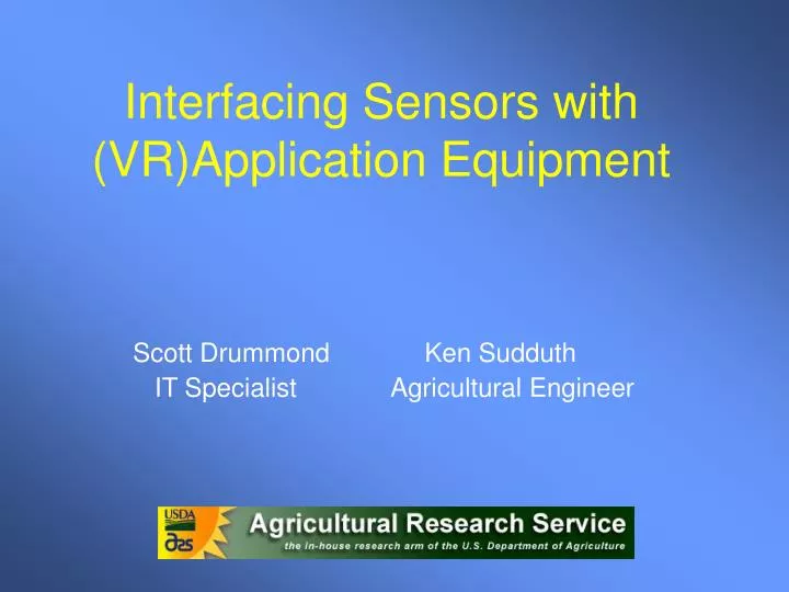
Interfacing Sensors with (VR)Application Equipment. Scott Drummond Ken Sudduth IT Specialist Agricultural Engineer. Objectives. Understand the “big picture” of developing a sensor based system for VRA of N.

E N D
Interfacing Sensors with (VR)Application Equipment Scott Drummond Ken Sudduth IT Specialist Agricultural Engineer
Objectives • Understand the “big picture” of developing a sensor based system for VRA of N. • Recognize design details that often get ignored or at least “underappreciated”. • See how these details affect the design and development of one such research system.
Crop Sensing • Remote sensing • Satellite based • Aerial based • Real time sensing • Passive Sensors • Active Sensors
Active Sensors • By using an internal light source, these sensors eliminate problems with sun angle and cloud variations • GreenSeeker by NTech • Crop Circle by Holland Scientific • CropSpec by Topcon
Effect of soil on active sensors? V7 corn with 0 N
Is soil an important part of the signal?Do we need to consider a way to remove the effect of soil?What happens when the soil “color” varies across time or across the landscape?
Stability of sensor readings? Courtesy: Dr. Peter Scharf
Variable Rate Controllers • Things you must consider when selecting the controller for your VRA system… • VRA control type • Range of rates • Response time • Precision and accuracy • Communication method(s)
Variable Rate Controllers • Many systems claim VRA control but… • Real time control • Message based • Controller includes decision module • Map based control • Useful for image based methods – much less attractive for active sensor applications
Variable Rate Controllers • Range of rates for: • Dry fertilizers • Range generally not an issue • Liquid fertilizers • Standard pressure regulated • Capstan spray system (PWM) • SprayTarget variable flow nozzles
Variable Rate Controllers What COULD happen IF our response time was too slow?
Variable Rate Controllers • Communication issues • Serial (RS-232/RS-422/RS-485) • CAN Bus • As applied maps – stored where/how? • Message formats can be open or proprietary
Decision Module • Things to consider when selecting the decision module for your VRA system… • Communication • Algorithm(s) • Flexibility
Decision Module • Questions to ask yourself… • How many algorithms are available? • Is my algorithm “stable”? • Can I adjust (timing/layout/parameters)? • What happens when a new piece of information (sensor/map) appears?
Designing a VRA System • Now that we have an idea of some of the questions to ask… let’s look into the design of a system based upon a set of requirements. • This system was designed for research applications, and may have more stringent requirements than some.
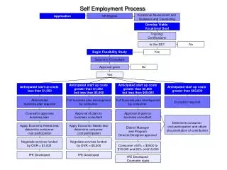
Requirements • Use existing Spra-Coupe • Plot sizes down to 5x10 m in size • Range = 0-210 lb/a N • Precision = 30 lb/a • Accuracy < 5% of full scale. • Map based and sensor based VRA needed • GS & CC sensor data collected and/or used • Algorithm – complete flexibility needed
Application System • Used existing AGCO Fieldstar controller in the SpraCoupe to change system operating pressure to compensate for changes in ground speed. • To get fast response, we chose a “bypass” or 3-way valve system. • When a particular valve (1x, 2x, or 4x) was not sending N to the ground, that same volume of flow was returned to the sprayer tank through a matched orifice. • The pump was always putting out the same volume at the same pressure, and the pressure control system did not have to respond (at least theoretically).
Application System • We chose a 6-row system for reasonable plot widths • Near maximum capacity of the SpraCoupe pump at normal operating speeds • Drop nozzles with 1x, 2x, and 4x orifice plates were installed in row middles • Nominal application rates: • 1x = 30 lb N/acre • 2x = 60 3x = 90 • 4x = 120 5x = 150 • 6x = 180 7x = 210
Data Flow Prior to Application Green GreenSeeker 1 Green GreenSeeker 2 Crop Circle 3 Crop Circle 4 Collect Reference Strip Data Select and/or Combine Sensor Outputs Interpolate/ extrapolate whole-field reference map Get Reference Value at Current Point Spatial or time-base filtering Solenoid Valve Control N Recommendation Algorithm Smoothing, Deadband, Hysteresis Get Current GPS data Decision Module 0, 1x, 2x, 3x, 4x, 5x, 6x, or 7x
a b Drop Nozzles N Sensors Finding the target sensor data… Given that: Sensor data buffered at 10 Hz v = GPS velocity (m/s) a+b = dist from sensors to drops (m) L = system latency (s) The target sensor data was taken this many readings ago… t = 10*(((a+b)/v)+L) In practice, we have averaged 1s of data (10 values per sensor) centered around this target point.
Positioning details… a b Drop Nozzles N Sensors c Sensor Boom Location esens = cos(90-h)*a+egps nsens = sin(90-h)*a+ngps Application Boom Center eboom = cos(90-h)*b+egps nboom = sin(90-h)*b+ngps d Individual Sensor Locations eright = cos(90-(h+atn(c/a))*sqrt(c2+a2)+egps nright = sin(90-(h+atn(c/a))*sqrt(c2+a2)+ngps eleft = cos(90-(h-atn(d/a))*sqrt(d2+a2)+egps nleft = sin(90-(h-atn(d/a))*sqrt(d2+a2)+ngps GPS Antenna Gives Easting(x), Northing(y), h(eading) and v(elocity)
Software Control Loop… Collect store and buffer data: sensors, GPS, psi, status, etc. Find Target Data Find N-Ref Data Calc Raw N-Rate Time >1s? N-Rate < MIN? Yes Yes N-Rate = MIN No No N-Rate > MAX? Yes N-Rate = MAX No Map to 0X-7X Beyond Deadband? Yes Send New Rate To Controller No
How Well Did it Work ? • Accuracy and consistency of response