Download
1 / 26
740 likes | 1.5k Views
Environment. System. ECE362 – Principles of Design The System Engineering Process. High Level Design. Unit Overview. Inside versus outside Design decomposition, synthesis High level design is physical architecture Tracing requirements to design Detail design

E N D
Environment System ECE362 – Principles of Design The System Engineering Process High Level Design
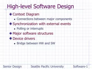
Unit Overview • Inside versus outside • Design decomposition, synthesis • High level design is physical architecture • Tracing requirements to design • Detail design • Host Company standard design architectural patterns
Environment System Inside versus outside Requirements • Statements at the external boundary • What we want the system to be or do, seen externally
Environment System Inside versus outside Design • Statements about internalphysicalcomponents and theirinteractionrelationships • How we are going to meet requirements
Design statement Requirement statement Detailed design statement Detailed requirement statement More detailed design statement More detailed requirement statement Design Interfaces Requirements I Environment I System Inside versus outside Inside versus outside Detail does not equal design
Environment System Inside versus outside Inside vs. outside, continued • Reference boundaries • One person’s design is another person’s requirement
Inside versus Outside In the following sections, we will refine our understanding of the meaning of “inside” and “outside”, by considering: • System boundaries and interiors (“who”) • Function boundaries and interiors (“what”) • State boundaries and interiors (“when”)
Uniform bookkeeping language • There is a tendency to record designs in a different language from that used to express requirements. • In particular, to record designs in technology-specific languages • This causes problems of communication and understanding across groups and job functions. • Technology-specific language can cloud the structure of a design, and obscure its connection to requirements. • Remember, what is a design for one person is a requirement for another, so language ought not shift.
Uniform bookkeeping language • A big surprise: High level designs can be recorded in exactly the same language as requirements: • Who: who are the internal components? • What: what are the functional interactions between these components? • When: when do these interactions occur? • This is the same language that expressed interactions of the subject system with its external environment/actors. • This improves communication and understanding. • In particular, it makes tracing external requirements to internal architecture much easier--improving everyone’s understanding.
Uniform bookkeeping language • This does not prevent us from recording detail designs in technology-specific languages--and we should do so; e.g., • electronic schematics • program design • mechanical drawings • hydraulic schematics • But, it means that each such design should have its high level design (physical architecture) recorded in the uniform language of system engineering. • This expresses high levelorganization as a framework for later detail design, and across different technologies that must be integrated. • It connects design to the requirements it supports.
Design Decomposition • System decomposition divides a system into sub-systems: • dividing who does things; pulls apart systems • Functional decomposition divides a function into sub-functions: • dividing what gets done; pulls apart functions • State decomposition divides a state into sub-states: • dividing when things happen; pulls apart time
Function Allocation • Function Allocation allocates the “whats” to the “whos” and “whens”: • which sub-systems perform which function roles (who) • in which sub-states functions are to occur (when)
Decomposition: Synthesis and Analysis • There are infinitely many ways to divide and allocate these. • This division process is synthesis--often a creative act. • May be viewed as a kind of unfolding of the structure of the system, in three (or more) dimensions.
Customer/Market Needs Available Technologies Design Specification (“Design”) Requirements Specification (“Analysis”) design impacts requirement structure refinement refinement Decomposition: Synthesis vs. Analysis We check potential solutions by analysis, to see if they meet requirements.
Synthesis • Synthesis is challenging when there is no familiar design pattern (decomposition) that satisfies the given requirements. • Known patterns of architecture, or even known useful components, can help this process. • This can include analogy • A family pattern of architecture for the subject system can help even more: • Changes the problem from synthesis to re-use, configuration, and analysis
Environment System Synthesis methods • While differing in specifics, all these methods have same goals: • Establish a set of internal physical subsystems and their organizing framework of interactions • Allocation of external interactions (functional requirements) to them • Optimization of trade-offs to meet various objectives and constraints • So, even though different methods may produce different design solutions, the form of the information they produce is the same: • The high level design of the system • And allocation of requirements onto that architecture
Functional analysis vs. synthesis • The term “analysis” is used in two different ways: • Requirements analysis (or functional analysis): • Analyzes the functional requirements of a system, decomposing them into logical architecture that is still short of a design, but begins to hint at a design. • This is the logical architecture discussed in the Requirements unit. • Analysis of design: • After a design has been synthesized, this kind of analysis studies the characteristics of that design • e.g., by simulation, mathematics, reasoning, constructing prototypes, etc. • These are certainly not the same thing!
Functional requirements • Functional requirements are the relationship between system inputs and system outputs : • In linear systems, this reduces to the system’s transfer function. • Most systems aren’t linear, but the general statement still holds for all of them. • This relationship is therefore encoded in words, tables, graphs, mathematics, fuzzy statements, and other forms. • But, it is still the formal relationship of inputs to outputs:
Example: PID Controller (proportional, integral, derivative) • The diagram expresses the external mathematical relationships of inputs and outputs—equivalent to a differential equation. • But, this does not say whether the result is to be obtained by allocation onto analog electronics, a DSP chip, a mechanical Bush Differential Analyzer, a block oriented simulator, nor the order of differentiation and integration around the loop. • It expresses external requirements, not internal design.
Implications for creative design solutions • “Thinking outside the box” has come to mean thinking of solutions to requirements that are outside of expected paradigms. • Suppose instead that you let “the box” stand for the boundary of the Subject System. • If you draw a logical architecture inside the box, you are really expressing a way of thinking about the external functional relationships. • Different decompositions suggest different design solutions when these are allocated onto physical components. • So, you can “think outside the box” (think about external relationships) by drawing inside the box!
High Level Design Is Architecture • Architecture is a listing of a system’s major components and relationships • Simple patterns to reduce complexity
Types of architecture • A single system has multiple architectures. • Each architecture is a different view of what is considered to be the major components and relationships of a system. • Each view is from a different perspective: • Example: Architecture of a building, viewed by occupant, electrical/mechanical contractor, and janitorial services contractor.
Types of architecture • Examples of types of architecture: • Physical architecture • Logical architecture • Manufacturing architecture • Shipping and storage architecture • Service, maintenance, support architecture • Embedded intelligence architecture • Project architecture • “Views of Systems”
Conceptual Design • Generate Ideas on how to implement the PDS • Evaluate the Ideas as to which is the best way to implement the PDS
Detail Design • This is type of design in the core ECE courses • Decomposition is repeated in successive stages • Detail Design follows High Level Design • Technology-specific aspects appear: • Electronic parts • Software modules • Mechanical components • etc. • Where system engineering meets technology specific engineering disciplines
Systematica, Gestalt Rules, Return on Variation are trademarks of System Sciences, LLC.