Download
1 / 30
300 likes | 628 Views
CMPT 275 High Level Design Phase Architecture. Objectives of Design. The design phase takes the results of the requirements analysis phase and evolves these results further Use cases and use case diagrams Context diagram, requirements, class diagrams, state diagrams …

E N D
Objectives of Design • The design phase takes the results of the requirements analysis phase and evolves these results further • Use cases and use case diagrams • Context diagram, requirements, class diagrams, state diagrams … • The results of the design phase feeds directly into the implementation phase • Requirements analysis → WHAT the system must do • Next Goal: determine HOW the software system is to accomplish what it must do
Map of design phase DESIGN object design or System design or LOW LEVEL DESIGN HIGH LEVEL DESIGN Data Persistance Subsystem Classes Class Interfaces Interaction Diagrams Module Interfaces Modularization architecture User Interface User Manual Implementation
System design activities Functional requirements Non Functional requirements Analysis Analysis dynamic model Analysis object model System design Design goals Subsystem decomposition Object design
Objectives of system design • Transforms analysis model (from requirements analysis) into a system design model • System decomposition • Identify design goals (choose aspects of the system to be optimized) • Develop and refine a subsystem decomposition that satisfies the maximum number of design goals and or the most critical design goals • Identify, model system architecture
Some Architectural Styles • Data Flow (Pipes and Filters) • Follow the flow of data through the system • Call and Return • Single thread of control as a main program calling subprograms then returning when done • Repository (data-centered) • One or more modularized subsystems that interact only with a central data repository • Services divided into layers, communication between adjacent layers.
Some Architectural Styles • Client-server • One or more servers with different purposes, which can be used by a group of clients that need their services. Usually connected by a network. • Layered • Services divided into layers, communication between adjacent layers. • Model / View / Controller • Model captures an application specific model • An independent controller sequences operations
Pipes and filters: Simplest case • Batch sequential • Pipe (line with arrow) represents a data flow in the direction of the arrow • Each filter (oval) represents some kind of manipulation of the data • The output of one filter is used as the input of the next filter • Commonly used model in the UNIX operating system
Pipes and filters • Can deal with more complex systems that have multiple paths through them
Pipes and filters: advantages • Can evolve easily by adding new filters • Simple to implement and maintain, Can reuse filters • Intuitive, think of a task in terms of steps • Well suited to systems that apply transformations to a stream of data
Pipes and filters: limitations • Needs a common format for data transfer • If formats of output/input of filters vary only some filters can be paired • Filters in a system must agree on a common data format, individual filters must then translate that format into what they need internally (can be inefficient) • e. g. UNIX uses character strings
Pipes and filters: Invoice processing Invoices Payments Identify Payments Find Payments Due Read invoices Issue Receipts Issue Payment Reminder Receipts Reminders From figure 11.6 Sommerville 2004
main Call and Return • Hierarchical transfer of control between processes • Control passes from the calling process to the called, then when the called process is complete, back to the called process
Repository Architecture • All subsystems interact only with a central data repository • Subsystems will themselves be modularized • A cohesive group of modules are often grouped into a subsystem • An efficient way to store large quantities of data • No need to transmit data directly between subsystems • Data used by a subsystem always from the repository • Data produced by a subsystem stored in the repository
Repository Architecture • Data is stored with one format • Format must be common to all modules. This enforces compromises on the form of the data which may effect efficiency of some modules • Can be difficult to change (evolve) the format of the data • Some activities are centralized with the repository and must be consistent for all subsystems • Access control, Security, Backup
Repository Subsystem 1 Subsystem 4 Subsystem 5 Project Repository Subsystem 2 Subsystem3
Repository architecture • If the repository is a passive object, it only interacts with subsystems when the subsystems request it • However, the repository may be an active object that can request actions from the other subsystems in the system. • When the repository initiates actions of the other subsystems then the architectural style is know as a blackboard system.
Code Generator Design Editor Program editor Project Repository Design Translator Design Analyser Report Generator Example Repository: CASE Tools CASE: Computer Aided Software Engineering From figure 11.2 Sommerville 2004
Client Server Architecture • A set of one or more servers provide services to other subsystems • Print server • File server • Data base server • A set of clients (often client is a subsystem) use the services provided by the servers. • Concurrent operation of more than one client is possible • The clients and servers are connected by a network (optional can all exist on one host but usually are distributed between several hosts)
Client-server Client subsystem 1 Client subsystem 2 Client subsystem 3 NETWORK (or IPC on one host) Server subsystem 1 Server subsystem 2
Client subsystem 1 Client subsystem 2 Client subsystem 3 Internet Catalogue server Library Catalogue Video server Film Clip Files Picture server Digitized Photos Web server Film and photo info Client-server From figure 11.3 Sommerville 2004
Client-server GameServer GameClient Internet GameClient GameClient
Advantages/Disadvantages • Well suited for systems that manage large amounts of data. (distributed or multiprocess) • Can be generalized to a peer-peer architectural style where each subsystem can both provide and request services • Can be seen as a special case of the repository where the central data store is managed by a process • Gives more flexibility, subsystems can different access control, security, backup as controlled by managing process
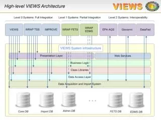
Layered Architecture • Subsystems are seen as layers • Layers can be independently developed, updated, replaced, subdivided. • Each layer implements a set of services not offered by other layers • In a closed layered architecture there is no communication between layers that are not adjacent. So only adjacent layers are effected if the inter subsystem interface changes
Closed Layered Model Layer 4 t Layer 3 X NO communications between non-adjacent layers Layer 2 Layer 1
Open Layered Model Layer 4 t Layer 3 A layer can communicate with any layer below it Layer 2 Layer 1
The OSI Layers: Layered Model CORBA TCP/IP Ethernet Expanded from Figure 1.10 Stallings (2000)
Multi Tier Layer 4 Presentation client Browser Layer 3 Presentation server Form Layer 2 Applications Logic Connection Layer 1 Storage query
Model/View/Controller • Model: maintains all domain knowledge • Controller, manages sequence of interaction with the user • View: Display model to user Controller initiator repository Model 1 Notifier View Subscriber *