Download
1 / 11
110 likes | 123 Views
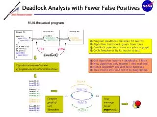
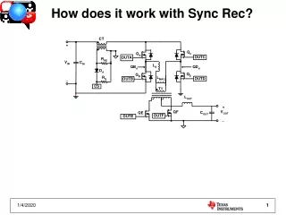
This article explains the T1 current flow in a Sync Rec system, including the intervals, when specific switches turn on and off, and the role of body diodes. It also addresses common misconceptions and provides insight into the actual T1 currents observed in an EVM.

E N D
Understanding T1 Currents • Interval 1 • QA, QD, QF on • QB, QC, QE are off • Energy delivered from primary -dILOUT/2
Understanding T1 Currents • Between Interval 1 and 2 • QD turns off and QDd LC Tanks • QC’s body diode will conduct -dILOUT/2
Understanding T1 Currents • Interval 2 • QC and QE turn on • QC body diode stops conducting -dILOUT/2
Misconception • Interval 2 • Misconception • QE and QF equally split current • When T1 Primary Shorted by QA and QC • Turns ratio forces most of I through QF • ΔILOUT is forced/divided through both windings -dILOUT/2
Understanding T1 Currents • Between Interval 2 and 3 • QA and QF turn off and QBd LC Tanks • QB’s body diode will conduct
Understanding T1 Currents • Interval 3 • QB turns on • Energy delivered from primary • QB’s body diode stops conducting
Understanding T1 Currents • Between Interval 3 and 4 • QC turns off and QDd LC Tanks • QD’s body diode will conduct
Understanding T1 Currents • Interval 4 • QD and QF turn on • QD body diode stops conducting
Understanding T1 Currents • Between Interval 4 and 1 • QB turns off and QBd LC Tanks • QA’s body diode will conduct • The cycle will start all over again