Fox Hunting: The Exciting World of Amateur Radio Direction Finding (ARDF)
240 likes | 272 Views
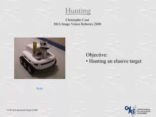
Learn about the art of fox hunting in amateur radio—locating hidden transmitters using directional equipment and skill, a recognized sport in Europe. Explore challenges, equipment, and techniques for successful hunts.

Fox Hunting: The Exciting World of Amateur Radio Direction Finding (ARDF)
E N D
Presentation Transcript
Fox Hunting Calvert Amateur Radio Association March 1, 2012 N3AE
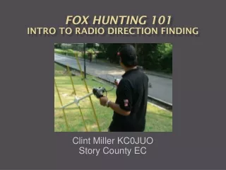
What is Fox Hunting(Amateur Radio Direction Finding - ARDF) • Locating a hidden transmitter using direction finding equipment and skill. • typically 2 meters and 80 meters • Is a recognized sport in Europe • not limited to Amateur Radio operators • Can involve a time constraint • points for fastest “finds” • Can involve elements of “orienteering” • compass & map • Skills apply to finding Emergency Locator Transmitters and interference sources as well
Challenges • Direction finding in multipath propagation environment • Multiple transmitters time-shared on same frequency, each on for only a period of time • Finding a well hidden “fox” in the RF “near field” • like geo-caching, people get inventive hiding the transmitter • Terrain difficulties & search strategy • Physical condition of the hunter
Equipment(2 Meter) • Directional Antenna • Yagi or Quad • HT or receiver • Signal Strength Output • meter or bar graph • “audio s-meter” • tone varies with strength • Attenuator • for “close-in” work Home brew “tape measure” yagi
Directional Antenna • Sharp forward lobe with low back and side lobes From WB2HOL Optimized Tape Measure Beam for Radio Direction Finding http://theleggios.net/wb2hol/projects/rdf/tape_bm.htm
Equipment(2 Meter continued) • Time Direction of Arrival (TDOA) • Sharp null when plane of antennasat right angle to transmitter • Bi-directional unless equippedwith a separate sense antenna • Fox could be ahead or behind • Simple & Inexpensive • Good entry level system • “Handy Finder Kit • May still be available for $27.95 at: http://www.handi-finder.com/
TDOAPrinciple of Operation Circuit switches between the two antennas at an audio rate ( 1 kHz or so). Since most FM demodulators are sensitive to signal phase as well as signal frequency, an audio tone will be generated if the two signals are not in phase. Amplitude of tonedepends on how much out of phase.Minimum amplitude for in-phase. Transmitter Position 1 Transmitter Position 1 Distance between transmitter and both antennas different if plane of antennas not at right angle to transmitter. Signal arrives at both antennas with phase difference. Distance between transmitter and both antennas equal if plane of antennas at right angle to transmitter. Signal arrives at both antennas in phase. Vertical Dipoles Spaced < ¼ Wavelength
Equipment(2 Meter continued) • Doppler Systems • typically vehiclemounted • Can use sophisticatedsignal processing • Can be tied intoGPS and mapsoftware
DopplerPrinciple of Operation Doppler Principles (Courtesy of WB6EYV)
DopplerPrinciple of Operation Doppler Shift as System Switches Antennas
DopplerPrinciple of Operation Doppler Principles (Courtesy of WB6EYV) To generate a significant amount of Doppler shift, ( about 500 Hertz at 144 MHz ) the antennas must be switched very fast... about 7.5 KHz in this D/F. With eight antennas, sequentially switched at 7.5 KHz, the rotation rate of the hypothetical antenna is 7500 / 8 = (approx.) 470 Hz. If the antennas are arranged in a circle with a two foot diameter, this simulates the movement of a single antenna which is circling at a ( tangential ) speed of 3000 feet per second.... nearly three times the speed of sound. The antenna switching is achieved with diodes, to deal with the high switching rates. Audio filtering is required to remove any voice modulation, and to construct a Doppler sine wave with enough waveform quality to be useful. The filtered Doppler sine wave has two zero-crossing "events", which occur when the hypothetical antenna is "nearest to" the signal source, and "farthest from" the signal source. ( Figure 2 ) The "nearest to" zero crossing always occurs at the end of the positive half cycle, ( "falling edge" zero - crossing ) and it can be detected and used to signal the exact instant when the hypothetical antenna is closest to the transmitter signal.
Equipment(80 Meter) • Almost always a magnetic loop antenna or ferrite bar antenna • sense antenna to resolve by-directional ambiguity Magnetic (shielded) loop http://www.foxhunt.com.au/
Magnetic Loop AntennaPrinciple of Operation http://www.wb8wfk.com/foxfinder80.html
Multipath • Problem above ~ 30 MHz • object can be a reflector if larger than ~ ½ wavelength • ½ wavelength is 3.4 ft • Not an issue for 80 Meters • not may objects big enough to be good reflectors • ½ wavelength is 140 ft • Am I picking up the bearing to transmitter or bearing to a reflection of the transmitter (or a reflection of a reflection, “hall of mirrors”)?
APRS and ARDF • Some equipment (usually Doppler) has provisions for automatically outputting bearing to an APRS message with the current user location • Multiple mobile/fixed stations can “share the hunt”
APRS and ARDF http://personalpages.tds.net/~tcweeden/aprs/aprs9909.htm http://www.usna.edu/Users/aero/bruninga/dfing.html
Fixed Station HF RDF(Adcock Interferometer) http://www.iw5edi.com/ham-radio/?the-adcock-hf-rdf-antenna,92
“Professional” Direction Finding • FCC Columbia Maryland Operations Center • multiple remote receiver sites • can analyze, fix and report the approximate location of a any high-frequency emitter with a very high level of accuracy, in seconds http://transition.fcc.gov/pshs/about-us/high_frequency_finding_center.html
“Professional” Direction Finding • Military • Huge HF direction finding arrays from cold war days • AN/FLR-9 Wullenweber (or Wullenwever) circularly disposed antenna array – over 1000 ft diameter • Sometimes called an Elephant Cage; now obsolete
ARDF Resources Joe Moell K0OV http://www.homingin.com/THRDFSinfo.html Good top level sites with links: http://www.homingin.com/ http://www.arrl.org/direction-finding http://ka7oei.com/ardf_pages.html http://www.ardf-r2.org/en/ Doppler & TDOA Systems http://www.qsl.net/ve2emm/index.html#index http://www.kn2c.us/ http://www.handi-finder.com http://www.silcom.com/~pelican2/ http://www.ramseyelectronics.com/ http://webhome.idirect.com/~griffith/tdoa.htm APRS & Direction Finding http://www.aprs.net/vm/DOS/DF.HTM