Download
1 / 31
310 likes | 493 Views
Modeling, Simulation, and Analysis of Variable Frequency Transformers. Brian C. Raczkowski Peter W. Sauer. Overview. Power Flow Control Langlois Converter Project Derivation of Model Small Power System Case Experimental Case Future Work. Ways to control power flow.

E N D
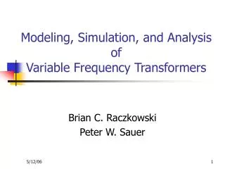
Modeling, Simulation, and Analysis of Variable Frequency Transformers Brian C. Raczkowski Peter W. Sauer
Overview • Power Flow Control • Langlois Converter Project • Derivation of Model • Small Power System Case • Experimental Case • Future Work
Ways to control power flow • Prime mover and excitation control of generators • Open and Close Breakers • Reactive Power Compensation
Ways to control power flow (cont.) • High Voltage DC (HVDC) • Rectifies AC to DC then inverts DC to AC • Economical for long distances • Harmonics • Isolation • Frequency
Ways to control power flow (cont.) • Transformers • Tap-Changing-Under-Load (TCUL) Transformers • Ability to change the ratio of transformation while energized • Requires additional circuitry • Phase shifting transformer • Addition of “90° out of phase” voltage • Useful for controlling real power • Most cases there is a fixed range
Drawbacks of These Methods • Set minimum and maximum constraints • Fixed change • Power transfer frequency requirement • Harmonics
Another Kind of Transformer • Induction machine • Squirrel cage rotor • Conducting bars laid in slots and shorting rings • Wound rotor • 3Φ windings with mirror images of windings on stator
Another Kind of Transformer (cont.) • Doubly-Fed Induction Machine (DFIM) • Rotor end not shorted • Wound rotor machine with access to rotor windings • Slip rings provide connection to rotor • Typically used to alter torque-speed curve • Same as Variable Frequency Transformer (VFT)
VFT Advantages • Continuous and no fixed set change points • Response for stability purposes • Simple model for power system use • HVDC alternative • Can transfer power at different frequencies • More control of the real power flow
VFT Disadvantages • Limits on maximum power flow capability • More lossy especially in reactive power losses • Works at low kV range so it needs step up/down transformers
Langlois Converter Project • GE investigated a new power transmission technology (2002) • Variable Frequency Transformer (VFT) • Controllable, bidirectional transmission device with ability to transfer power between asynchronous networks
World’s First VFT • Hydro-Quebec’s Langlois substation • Exchange +100MW to -100MW between power grids of Quebec (Canada) and New York (USA) • Closed Loop Control System to increase or decrease power delivery to maintain stability
General VFT • Core technology is rotary transformer with three phase windings on both rotor and stator • Continuously variable phase shifting transformer • Uses 2 transformers, a switched capacitor bank and a DC motor • Change rotor angle to change the power flow through the machine • Limits of the phase angle can be set as large as needed
Model Derivation • The machine is assumed to be a two-pole three phase machine with an a:1 turns ratio
Small Power System Case Glover and Sarma example
Small Power System with 3 VFTs Line 1 Line 2 Line 3 Just by inserting VFTs, the flows have changed
Experimental System Setup • GE I689, 7.5 hp, 3Φ, 6-pole induction machine • 2.93:1 turns ratio
Experimental System Notes • Variac used to match odd turns ratio • Slack Bus was the standard wall outlet • Load is purely resistive 12.8Ω • Source had 10A fuses • 1° mechanical was 3° electrical • Verification in PowerWorld Simulator • Voltage - 1000x • Power – 1e6x
Make Things Better • System is already inherently lossy • Add a capacitor bank to cut reactive losses • 121.5µF to each phase at Bus 3 • Current reduced from 7.03Arms to 2.45Arms • Needed 61.32V to achieve 7.05Arms • For comparative purposes Vin=20.4Vrms
Interesting Cases • Results verified in Power World Simulator
VFT Conclusions • Alternative method to control power flow • Easy model • Use in small power system case • Use in experimental power system case
Future Work • Larger Test Systems • Higher Voltage • Torque Analysis • Multiple Frequencies • Stability of the System • Economical Impact
Questions • Questions??