Modeling of Power Transformers
290 likes | 809 Views
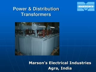
Modeling of Power Transformers. A Static Device. Transformers. The transformer enables us to utilize different voltage levels across the system for the most economical value.

Modeling of Power Transformers
E N D
Presentation Transcript
Modeling of Power Transformers A Static Device
Transformers • The transformer enables us to utilize different voltage levels across the system for the most economical value. • Stepping up the generator voltage to high voltage, is done through power transformers to minimize losses and increase the transmission capacity of the lines. • This transmission voltage level is then stepped down in many stages for distribution and utilization purposes.
General Theory • A transformer contains two or more windings linked by a mutual field. • The primary winding is connected to an alternating voltage source. • The input current results in an alternating flux whose magnitude depends on the voltage and number of turns of the primary winding. • The alternating flux links the secondary winding and induces a voltage in it with a value that depends on the number of turns of the secondary winding.
Transformers Basic components of single phase transformer
Transformers 5.2 Single phase transformer arrangement
Transformers Polarity for transformer
Transformers Small transformer construction a) Lamination b) Iron core with winding
Transformers Dry-type three-phase transformer
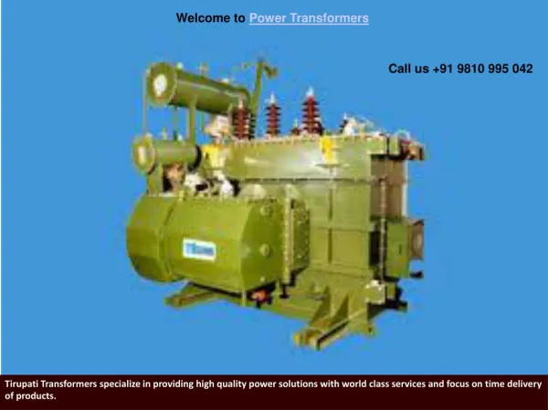
Transformers Oil Insulated and cooled transformer
Transformation ratio Primary (supply) Secondary (Load)
Transformers at no load Ic E1 IF Qc E1 If Im f IF Ic Im The no load current If is needed to supply the no load losses and to magnetize the transformer core.
Loaded Transformer Z2’ is the load impedance referred to the primary
Transformer losses • The transformer losses are divided into electrical losses (copper losses) and Magnetic losses (Iron losses). • Copper losses in both the primary and secondary windings. • Magnetic losses, these losses are divided into eddy current losses and hysteresis losses.
Equivalent circuit V1: Primary voltage (supply) I1 : Primary current. V2: Secondary voltage (load) I2: : Secondary current
Approximate Circuit (a) (b) The no load current ranges from 1% to 3% of the full load current. Therefore, the circuit can be simplified to circuit (b).
Performance Measures • The percent regulation • The transformer efficiency
Example A 100-kVA, 400/2000 V, single-phase transformer has the following parameters R1 = 0.01 R2 = 0.25 ohms X1 = 0.03 ohms X2 = 0.75 ohms The transformer supplies a load of 90 kVA at 2000 V and 0.8 PF lagging. • Calculate the primary voltage and current using the simplest equivalent circuit. • Find also the V.R. and efficiency for the transformer