Axes and Dimensioning
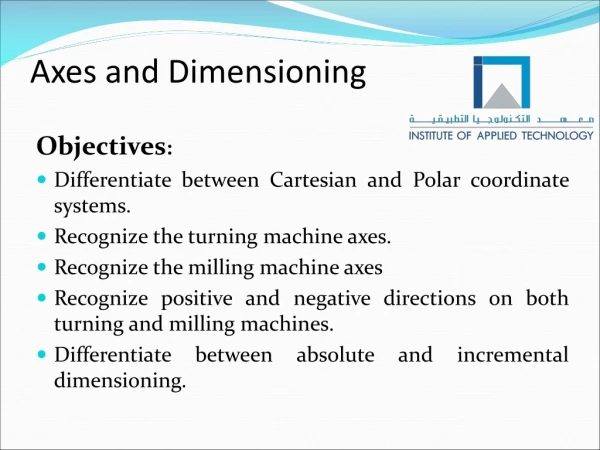
Axes and Dimensioning. Objectives : Differentiate between Cartesian and Polar coordinate systems. Recognize the turning machine axes. Recognize the milling machine axes Recognize positive and negative directions on both turning and milling machines.

Axes and Dimensioning
E N D
Presentation Transcript
Axes and Dimensioning Objectives: Differentiate between Cartesian and Polar coordinate systems. Recognize the turning machine axes. Recognize the milling machine axes Recognize positive and negative directions on both turning and milling machines. Differentiate between absolute and incremental dimensioning.
In order to shape a metal by machine tools, the cutting tool should move in contact with the workpiece at a certain specific points, while the workpiece or cutting tool is rotating. Coordinate Systems We need a coordinate system to know the current and target positions of the cutting tool. Axes
Coordinate Systems Basically there are two common coordinate systems: Cartesian coordinate system. Polar Coordinate system.
Cartesian Coordinate System Is used to describe the position of a point in the space.
When dealing with 2 dimensions (2D), the two-dimensional coordinate system is used.
When dealing with three dimensions (3D), the three-dimensional coordinate system is used;
Polar Coordinate System The point is located by its distance (radius r) to the point of origin and its angle (alpha α) to a specified axis. The angle is positive if it is measured in counterclockwise direction starting from positive X-axis. It is negative in clockwise direction.
CNC Machines’ Coordinate System Machine tool has its own "coordinate system“, to ensure that the control system of the machine will read the specified coordinates correctly. • Machine Zero Point (M) and Workpiece Zero point (W) are part of this system.
Machine zero point (M) is the origin of the coordinate system. It is defined by the manufacturer and cannot be changed. Machine Zero Point (M)
To indicate the position of the workpiece correctly and easily, machine zero point should be displaced to another point on the workpiece called workpiece zero point. Workpiece Zero Point (W)
Defined by the programmer. The workpiece zero point "W", can be specified as desired. Workpiece Zero Point (W)(Turning)
Workpiece Zero Point (W)(Milling) The workpiece zero point "W", can be specified as desired.
Turning Machine Axes +X +Z -Z - X CNC Turning machine has at least 2 controllable feed axes, marked as X and Z. )Turret is considered above the workpiece)
When the cutting tool moves toward and backward from the machine spindle, this is called movement along ………….. axis. When the cutting tool moves in cross direction to the longitudinal axis of the workpiece, this is called movement along …………… axis. When the tool moves away from the work part in Z axis, this movement is in………………. direction. When the tool moves away from the work part in X axis, this movement is in ………………..direction. Complete the following: Z X positive positive
Axes - Milling Machine +Z - X +Y - Y +X -Z A milling machine has at least 3 controllable feed axes, marked as X, Y and Z.
Describe the axes of vertical milling machine in your own words?
Dimensioning To machine a workpiece we need a technical drawing, on which we should write the required dimensions (information) to make the required shape. To dimension the workpiece we need to select a certain point on it, from which we should take the measurement. This point is the workpiece zero point (W).
Dimensioning There are two types of dimensioning: 1. Absolute Dimensioning: All measurements are taken from the workpiece zero point.
Dimensioning 2. Incremental Dimensioning: Uses incremental values that are always measured from the current point to the next point.
Write the coordinates of the points A,B,C,D and E shown on the absolute dimensioning below?
Solution 50 30 20 10 20 -25 30 -25 50 -25