Dimensioning
Dimensioning. Chapter 9. Objectives. Use conventional dimensioning techniques to describe size and shape accurately on an engineering drawing Create and read a drawing at a specified scale Correctly place dimension lines, extension lines, angles, and notes. Objectives (cont.).

Dimensioning
E N D
Presentation Transcript
Dimensioning Chapter 9
Objectives • Use conventional dimensioning techniques to describe size and shape accurately on an engineering drawing • Create and read a drawing at a specified scale • Correctly place dimension lines, extension lines, angles, and notes
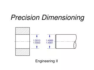
Objectives (cont.) • Use aligned and unidirectional dimensioning systems • Dimension circles, arcs, and inclined surfaces • Identify precision ranges for typical manufacturing operations • Apply finish symbols and notes to a drawing
Objectives (cont.) • Dimension contours • Use standard practices for dimensioning prisms, cylinders, holes, curves • List practices for dimensioning a solid model as documentation • Identify guidelines for the do’s and don’ts of dimensioning
Understanding Dimensioning • Drawings for products must be dimensioned so that production personnel all over the world can make mating parts that will fit properly when assembled or when used to replace parts
Aspects of Good Dimensioning • Dimensions are given in the form of distances, angles, and notes regardless of the dimensioning units being used • The ability to create good dimensions requires: • Technique of dimensioning • Placement of dimensions • Choice of dimensions
Tolerance • When a finished part is measured it may vary slightly from the exact dimension specified • Tolerance is the total amount that the feature on the actual part is allowed to vary from what is specified by the dimension
Lines Used in Dimensioning • Dimension line – a thin, dark, solid line terminated by arrowheads, indicating the direction and extent of a dimension
Lines Used in Dimensioning • Extension line – a thin, dark, solid line that extends from a point on the drawing to which a dimension refers
Lines Used in Dimensioning • Centerline – a thin, dark line alternating long and short dashes commonly used in locating holes and other symmetrical features
Using Dimension and Extension Lines • Shorter dimension lines are nearest the object outline • Dimension lines should not cross extension lines • A dimension line should never coincide with or extend any line of the drawing • Avoid crossing dimension lines when possible
Using Dimension and Extension Lines • Dimensions should be lined up and grouped together as much as possible
Using Dimension and Extension Lines • When extension lines or center lines cross visible object lines, gaps should not be left in the lines
Arrowheads • Arrowheads indicate the extent of dimensions • They should be uniform in size and style throughout the drawing
Leaders • A leader is a thin solid line directing attention to a note or dimension and starting with an arrowhead or dot
Drawing Scale and Dimensioning • Drawings are usually made to a scale which is indicated in the title block • A heavy straight line should be drawn under any single dimension value that is not to scale • If an entire drawing is not prepared to a standard, note NONE in the scale area of the title block
Direction of Dimension Values and Notes • All dimension values and notes are lettered horizontally and should read from the bottom of the sheet • The exception is when dimensioning from a baseline as in coordinate dimensioning
Dimension Units • Dimension values are shown using the metric system or decimal inch values • It is standard practice to omit millimeter designations and inch marks on drawings and note the units in the title block except when there is a possibility of misunderstanding
Dimension Units • Either meters or feet and inches and fractional inches are used in architectural and structural work • In U.S. structural and architectural drafting, all dimensions of 1 foot or over are usually expressed in feet and inches
Millimeter Values • The millimeter is the commonly used unit for most metric engineering drawings • One-place millimeter decimals are used when tolerance limits permit • Two or more-place millimeter decimals are used when higher tolerances are required
Decimal Inch Values • Two-place decimals are typical when tolerance limits permit • In two-place decimals, the second place preferably should be an even digit so that when the dimension is divided by 2 the results will still be a two-place decimal
Rules for Dimension Values • Where the metric dimension is a whole number, do not show a decimal point or a zero • Where the metric dimension is less than 1mm, a zero precedes the decimal point • Where the decimal-inch dimension is used, a zero is not used before the decimal point of values less than 1
Rounding Values • If the number following the rounding position is a 5, round to an even number • If the number following the rounding position is less then 5, make no change • If the number following the rounding position is more than 5, round up
Dual Dimensioning • Dual dimensioning is used to show metric and decimal inch dimensions on the same drawing
Placing Dimensions • Never letter a dimension value over any line on the drawing • In a group of parallel dimension lines, the dimension values should be staggered • Do not crowd dimension figures into limited spaces making them illegible
Placing Dimensions • Place dimensions between views when possible, but only attached to a single view • Dimensions should not be placed on a view unless doing so promotes the clarity of the drawing
Placing Dimensions • When a dimension must be placed in a hatched area or on the view, leave an opening in the hatching or a break in the lines for the dimension value
Placing Dimensions • Avoid dimensioning to hidden lines • Do not attach dimensions to visible lines where the meaning is not clear • Notes for holes are usually placed where you see the circular shape of the hole • An external cylindrical shape is dimensioned where it appears rectangular
Placing Dimensions • Give dimensions where the contours of the object are defined
Superfluous Dimensions • All necessary dimensions must be shown but avoid giving unnecessary dimensions • Do not repeat dimensions on the same view or on different views, or give the same information two different ways
Dimensioning Angles • You should dimension angles by specifying the angle in degrees and a linear dimension
Dimensioning Arcs • A circular arc is dimensioned in the view where you see its true shape by giving the value for its radius preceded by the abbreviation R
Fillets and Rounds • Individual fillets and rounds are dimensioned like other arcs • If there are only a few and they are obviously the same size, giving one typical radius is preferred • Fillets radii can also be given in a general note