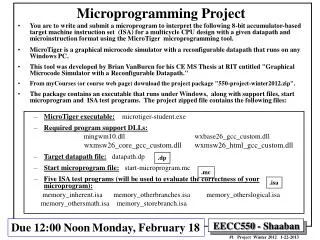
Microprogramming
Microprogramming. Krste Asanovic Laboratory for Computer Science Massachusetts Institute of Technology. Instruction Set Architecture (ISA) versus Implementation. ISA is the hardware/software interface Defines set of programmer visible state

Microprogramming
E N D
Presentation Transcript
Microprogramming Krste Asanovic Laboratory for Computer Science Massachusetts Institute of Technology
Instruction Set Architecture (ISA) versus Implementation • ISA is the hardware/software interface • Defines set of programmer visible state • Defines instruction format (bit encoding) and instruction semantics • Examples: DLX, x86, IBM 360, JVM • Many possible implementations of one ISA • 360 implementations: model 30 (c. 1964), z900 (c. 2001) • x86 implementations: 8086 (c. 1978), 80186, 286, 386, 486,Pentium, Pentium Pro, Pentium-4 (c. 2000), AMD Athlon, Transmeta Crusoe, SoftPC • DLX implementations: microcoded, pipelined, superscalar • JVM: HotSpot, PicoJava, ARM Jazelle, ...
ISA to Microarchitecture Mapping • ISA often designed for particular microarchitectural style, e.g., • CISC ISAs designed for microcoded implementation • RISC ISAs designed for hardwired pipelined implementation • VLIW ISAs designed for fixed latency in-order pipelines • JVM ISA designed for software interpreter • But ISA can be implemented in any microarchitectural style • Pentium-4: hardwired pipelined CISC (x86) machine (with somemicrocode support) • This lecture: a microcoded RISC (DLX) machine • Intel will probably eventually have a dynamically scheduled out-of-order VLIW (IA-64) processor • PicoJava: A hardware JVM processor
Microcoded Microarchitecture Microcode instructions fixed in ROM inside microcontroller busy? μcontroller zero? opcode Datapath Data Addr Memory enMem MemWrt Memory (RAM) holds user program written using macrocode instructions (e.g., DLX, x86, etc.)
A Bus-based Datapath for DLX busy Opcode zero OpSel ldA ldB ldIR ldMA MA RegSel addr addr IR 32 GPRs + PC ... ExtSel Memory Imm Ext MemWrt ALU control RegWrt ALU 32-bit Reg enReg enMem enImm data data enALU Bus Microinstruction: register to register transfer (17 control signals) MA ← PC means RegSel = PC; enReg=yes; ldMA= yes B ← Reg[rf2] means RegSel = rf2; enReg=yes; ldB = yes
Instruction Execution Execution of a DLX instruction involves • 1instruction fetch • decode and register fetch • ALU operation • memory operation (optional) • write back to register file (optional) and the computation of the address of the next instruction
Microprogram Fragments instr fetch: MA ← PC can be treated as a macro IR ← Memory A ← PC PC ← A + 4 dispatch on OPcode ALU: A ← Reg[rf1] B ← Reg[rf2] Reg[rf3] ← func(A,B) do instruction fetch ALUi: • A ← Reg[rf1] • B ← Imm sign extention ... • Reg[rf2] ← Opcode(A,B) • do instruction fetch
Microprogram Fragments(cont.) A ← Reg[rf1] B ← Imm MA ← A + B Reg[rf2] ← Memory do instruction fetch LW: A ← PC B ← Imm PC ← A + B do instruction fetch J: beqz: A ← Reg[rf1] If zero?(A) then go to bz-taken do instruction fetch bz-taken: A ← PC B ← Imm PC ← A + B do instruction fetch
DLX Microcontroller: first attempt Opcode zero? Busy (memory) μPC (state) latching the inputs may cause a one-cycle delay addr μProgram ROM 2(opcode+status+s) words word = (control+s) bits ROM Size ? How big is “s”? data next state 17 Control Signals
Microprogram in the ROM worksheet State Op zero? busy Control points next-state
Microprogram in the ROM State Op zero? busy Control points next-state
Microprogram in the ROM Cont. State Op zero? busy Control points next-state
Size of Control Store status & opcode μPC size = 2(w+s) x (c + s) Control ROM next μPC Control signals DLX w = 6+2 c = 17 s = ? no. of steps per opcode = 4 to 6 + fetch-sequence no. of states ≈ (4 steps per op-group ) x op-groups + common sequences = 4 x 8 + 10 states = 42 states ⇒ s = 6 Control ROM = 2(8+6) x 23 bits ≈ 48 Kbytes
Reducing Size of Control Store Control store has to be fast ⇒expensive • Reduce the ROM height (= address bits) ⇒ reduce inputs by extra external logic each input bit doubles the size of the control store ⇒ reduce states by grouping opcodes find common sequences of actions ⇒ condense input status bits combine all exceptions into one, i.e., exception/no-exception • Reduce the ROM width ⇒ restrict the next-state encodingNext, Dispatch on opcode, Wait for memory, ... ⇒ encode control signals (vertical microcode)
DLX Controller V2 absolute ext Opcode μPC+1 μPC Reduced ROM height by encoding inputs μPCSrc μPC (state) zero jump logic buzy Control ROM Reduce ROM width by encoding next-state μJumpType (next, spin, fetch, dispatch, feqz, fnez ) 17 Control Signals
Jump Logic μPCSrc = Case μJumpTypes next ⇒ μPC+1 spin ⇒ if (busy) then μPC else μPC+1 fetch ⇒ absolute dispatch ⇒ op-group feqz ⇒ if (zero) then absolute else μPC+1 fnez ⇒ if (zero) then μPC+1 else absolute
Instruction Fetch & ALU: DLX-Controller-2 State Control points next-state fetch0 MA ← PC next fetch1 IR ← Memory spin fetch2 A ← PC next fetch3 PC ← A + 4 dispatch ... ALU0 A ← Reg[rf1] next ALU1 B ← Reg[rf2] next ALU2 Reg[rf3]← func(A,B) fetch ALUi0 A ← Reg[rf1] next ALUi1 B ← sExt16(Imm) next ALUi2 Reg[rf3]← Op(A,B) fetch
Load & Store:DLX-Controller-2 State Control points next-state LW0A ← Reg[rf1] next LW1B ← sExt16(Imm) next LW2MA ← A+B next LW3Reg[rf2] ← Memory spin LW4fetch SW0A ← Reg[rf1] next SW1B ← sExt16(Imm) next SW2 MA ← A+B next SW3 Memory ← Reg[rf2] spin SW4fetch
Branches: DLX-Controller-2 • State Control points next-state • BEQZ0 A ← Reg[rf1] next • BEQZ1 fnez • BEQZ2 A ← PC next • BEQZ3 B ← sExt16(Imm) next • BEQZ4 PC ← A+B fetch • BNEZ0 A ← Reg[rf1] next • BNEZ1 feqz • BNEZ2 A ← PC next • BNEZ3 B ← sExt16(Imm) next • BNEZ4 PC ← A+B fetch
Jumps: DLX-Controller-2 • State Control points next-state • J0A ← PC next • J1B ← sExt26(Imm) next • J2PC ← A+B fetch • JR0PC ←Reg[rf1] fetch • JAL0A ← PC next • JAL1Reg[31] ← A next • JAL2B ← sExt26(Imm) next • JAL3PC ← A+B fetch • JALR0A ← PC next • JALR1Reg[31] ← A next • JALR2PC ←Reg[rf1] fetch
Microprogramming in IBM 360 • Only fastest models (75 and 95) were hardwired
Horizontal vs Vertical μCode Bits per μInstruction • Horizontal μcode has longer μinstructions • Can specify multiple parallel operations per μinstruction • Needs fewer steps to complete each macroinstruction • Sparser encoding ⇒ more bits • Vertical μcode has more, narrower μinstructions • In limit, only single datapath operation per μinstruction • μcode branches require separate μinstruction • More steps to complete each macroinstruction • More compact ⇒ less bits • Nanocoding • Tries to combine best of horizontal and vertical μcode μInstructions
Nanocoding Exploits recurring control signal patterns in μcode, e.g., μPC (state) μcode next-state • MC68000 had 17-bit μcode containing either 10-bit μjump or 9-bit nanoinstruction pointer • Nanoinstructions were 68 bits wide, decoded to give 196 control signals μaddress μcode ROM nanoaddress ALU0 A ← Reg[rf1] ... ALUi0 A ← Reg[rf1] ... nanoinstruction ROM data 17 Control Signals
Implementing Complex Instructions busy Opcode zero ldIR OpSel ldA ldB ldMA MA RegSel addr addr 32 GPRs + PC ... Memory ExtSel Imm Ext RegWrt MemWrt ALU 32-bit Reg enMem enReg data data enImm enALU Bus • rf3 ← M[(rf1)] op (rf2) Reg-Memory-src ALU op • M[(rf3)] ← M[(rf1)] op M[(rf2)] Reg-Memory-dst ALU op • M[(rf3)] ← (rf1) op (rf2) Mem-Mem ALU op
Mem-Mem ALU Instructions: DLX-Controller-2 Mem-Mem ALU op M[(rf3)] ← M[(rf1)] op M[(rf2)] ALUMM0 MA ← Reg[rf1] next ALUMM1 A ← Memory spin ALUMM2 MA ← Reg[rf2] next ALUMM3 B ← Memory spin ALUMM4 MA ← Reg[rf3] next ALUMM5 Memory ← func(A,B) spin ALUMM6 fetch Complex instructions usually do not require datapath modifications in a microprogrammed implementation --only extra space for the control program Implementing these instructions using a hardwired controller is difficult without datapath modifications
Microcode Emulation • IBM initially miscalculated importance of software compatibility when introducing 360 series • Honeywell started effort to steal IBM 1401 customers by offering translation software (“Liberator”) for Honeywell H200 series machine • IBM retaliates with optional additional microcode for 360 series that can emulate IBM 1401 ISA, later extended for IBM 7000 series • one popular program on 1401 was a 650 simulator, so somecustomers ran many 650 programs on emulated 1401s (650->1401->360)
Microprogramming in the Seventies Thrived because: • Significantly faster ROMs than DRAMs were available • For complex instruction sets, datapath and controller were cheaper and simpler • New instructions , e.g., floating point, could be supported without datapath modifications • Fixing bugs in the controller was easier • ISA compatibility across various models could be achieved easily and cheaply Except for cheapest and fastest machines, all computers were microprogrammed
Writable Control Store (WCS) Implement control store with SRAM not ROM • MOS SRAM memories now almost as fast as control store (core memories/DRAMs were 10x slower) • Bug-free microprograms difficult to write User-WCS provided as option on several minicomputers • Allowed users to change microcode for each process User-WCS failed • Little or no programming tools support • Hard to fit software into small space • Microcode control tailored to original ISA, less useful for others • Large WCS part of processor state -expensive context switches • Protection difficult if user can change microcode • Virtual memory required restartablemicrocode
Performance Issues Microprogrammed control ⇒ multiple cycles per instruction Cycle time ? tC > max(treg-reg, tALU, tμROM, tRAM) Given complex control, tALU & tRAM can be broken into multiple cycles. However, tμROM cannot be broken down. Hence tC > max(treg-reg, tμROM) Suppose 10 * tμROM < tRAM good performance, relative to the single-cycle hardwired implementation, can be achieved even with a CPI of 10
VLSI & Microprogramming By late seventies • technology assumption about ROM & RAM speed became invalid • micromachines became more complicated • to overcome slower ROM, micromachines were pipelined • complex instruction sets led to the need for subroutine and call stacks in μcode. • need for fixing bugs in control programs was in conflict with read-only nature of μROM ⇒ WCS (B1700, QMachine, Intel432, …) • introduction of caches and buffers, especially for instructions, made multiple-cycle execution of reg-reg instructions unattractive
Modern Usage Microprogramming is far from extinct Played a crucial role in micros of the Eighties, Motorola 68K series Intel 386 and 486 Microcode is present in most modern CISC micros in an assisting role (e.g. AMD Athlon, Intel Pentium-4) • Most instructions are executed directly, i.e., with hard-wired control • Infrequently-used and/or complicated instructions invoke the microcode engine Patchable microcode common for post-fabrication bug fixes, e.g. Intel Pentiums load μcode patches at bootup