Download
1 / 8
80 likes | 220 Views
1) Structural Symmetry 2) Bookshelf Problem. Jake Blanchard Fall 2009. Making Use of Problem Symmetry. Reflective or mirror symmetry exists if there is symmetry of geometry, loads, and properties with respect to a plane. Other symmetry types exist, but are less common

E N D
1) Structural Symmetry2) Bookshelf Problem Jake Blanchard Fall 2009
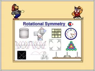
Making Use of Problem Symmetry • Reflective or mirror symmetry exists if there is symmetry of geometry, loads, and properties with respect to a plane. • Other symmetry types exist, but are less common • Another type – Axisymmetry uses special element formulations rather than boundary conditions and will be studied later in the course. Anti-symmetry Rotational Symmetry P
Using Symmetry • Using symmetry reduces problem size (also modeling time) and can simplify boundary conditions. Symmetry b.c. Symmetry b.c. p p p Or Symmetry b.c. Ux = 0 Rotz = 0
20 cm • E=200 GPa • =0.3 • Thickness=3 mm • Plane Stress • Fillet radius is 2 cm • p=0.2 MPa • Find max Von Mises stress 10 cm 2 cm
To easily vary fillet radius… • File/Write db log file… • Choose write essential commands only • Edit file and change radius • File/Clear and Start New • File/Read input from…
My Log File Listing ESIZE,0.0025,0, MSHKEY,0 CM,_Y,AREA ASEL, , , , 2 CM,_Y1,AREA CHKMSH,'AREA' CMSEL,S,_Y !* AMESH,_Y1 !* CMDELE,_Y CMDELE,_Y1 CMDELE,_Y2 !* FLST,2,2,4,ORDE,2 FITEM,2,2 FITEM,2,10 !* /GO DL,P51X, ,ALL, FLST,2,1,4,ORDE,1 FITEM,2,3 /GO !* SFL,P51X,PRES,.2e6, FINISH /SOL /STATUS,SOLU SOLVE FINISH /POST1 !* PLESOL, S,EQV, 0,1.0 /PREP7 !* ET,1,PLANE82 !* KEYOPT,1,3,3 KEYOPT,1,5,0 KEYOPT,1,6,0 !* !* R,1,.003, !* !* MPTEMP,,,,,,,, MPTEMP,1,0 MPDATA,EX,1,,200e9 MPDATA,PRXY,1,,0.3 BLC4,0,0,.2,.02 BLC4,.2,0,-.02,-.08 FLST,2,2,5,ORDE,2 FITEM,2,1 FITEM,2,-2 AADD,P51X !* LFILLT,9,8,.02, , FLST,2,3,4 FITEM,2,6 FITEM,2,7 FITEM,2,1 AL,P51X FLST,2,2,5,ORDE,2 FITEM,2,1 FITEM,2,3 AADD,P51X
Edited and Annotated Version /PREP7 ! enter preprocessor ET,1,PLANE82 ! specify plane82 as element type KEYOPT,1,3,3 ! with thickness option R,1,.003, ! real constant for 3mm thickness MP,EX,1,200e9 ! define elastic modulus MP,PRXY,1,0.3 ! define poisson's ratio BLC4,0,0,.2,.02 ! make a 20cm by 2cm block with bottom left edge at origin BLC4,.2,0,-.02,-.08 ! make a -2cm by -8cm block with bottom left edge at 20cm,0cm AADD,1,2 ! add areas 1 and 2 LFILLT,9,8,.02, , ! make a .02 cm fillet between lines 9 and 8 AL,6,7,1 ! make an area from lines 6,7 and 2 (fillet region) AADD,1,3 ! add areas 1 and 3 ESIZE,0.0025,0, ! set default element edge length to 2.5 mm MSHKEY,0 ! specify free meshing AMESH,all ! mesh all areas LSEL,s,loc,x,0.2 ! select all lines with centroid at x=20 cm DL,all, ,ALL, ! constrain these lines in all directions LSEL,s,loc,y,0.02 ! select all lines with centroid at y=2 cm SFL,all,PRES,.2e6, ! apply pressure on this line allsel,all ! select everything /SOL ! enter solution processor SOLVE ! solve problem /POST1 ! enter post processor PLESOL, S,EQV, 0,1.0 ! plot equivalent stress
Using Variables in Input Files • Plate with an offset hole /PREP7 ! enter the preprocessor len = 3 ! define full strip dimensions wid = 1 rad = .1 ! define hole radius and center coordinates xc = 0 yc = .25 ET,1,PLANE42 ! define element type as plane42 KEYOPT,1,3,3 ! specify constant thickness option MP,EX,1,10e6 ! Elastic modulus MP,PRXY,1,.3 ! Poisson's Ratio R,.1 ! Set real constant for thickness /PNUM,KP,1 ! Turn keypoint, line, and area numbering on /PNUM,LINE,1 /PNUM,AREA,1 BLC4,0,-wid/2,len/2,wid ! Create Rectangle CYL4,xc,yc,rad ! Create Circle ASBA,1,2 ! Subtract area2 from area1 SMRTSIZE,1 ! Set smartsize control to 1 MSHKEY,0 ! free meshing AMESH,all ! mesh all areas lsel,s,loc,x,0 ! select all lines on symmetry plane DL,all, ,symm, ! apply symmetry constraint nsel,s,loc,x,0 ! select nodes at x=0 nsel,r,loc,y,-wid/2 ! select from selected set nodes at y=-wid d,all,uy,0 ! fix selected node in uy to prevent rigid body motion lsel,s,loc,x,len/2 ! select lines on free edge SFL,all,PRES,-1000, ! apply pressure on lines allsel,all! select leverything /SOL ! enter solution processor SOLVE ! solve /POST1 ! enter general postprocessor PLNSOL, S,X, 0,1.0 ! plot x direction stresses FINISH len wid