Real-Time Image Motion Compensation System for MODS
10 likes | 89 Views
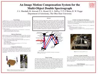
An innovative system for the Multi-Object Double Spectrograph (MODS) compensates for image motion, enhancing data quality by tracking and adjusting for movement during observations. Using an infrared laser reference beam and active mirror adjustments, image vibrations are minimized without affecting science data quality. Lab tests have demonstrated precise compensation mechanisms, ensuring accuracy and repeatability. Currently in prototype assembly, the system is set to be deployed with MODS at the Large Binocular Telescope in 2004. Supported by NSF grant AST-9987045 and the David G. Price Foundation fellowship.

Real-Time Image Motion Compensation System for MODS
E N D
Presentation Transcript
An Image Motion Compensation System for the Multi-Object Double Spectrograph J. L. Marshall, B. Atwood, P. L. Byard, D. L. DePoy, T. P. O’Brien, R. W. Pogge Department of Astronomy, The Ohio State University Abstract We describe a closed-loop image motion compensation system (IMCS) for the Multi-Object Double Spectrograph (MODS), which is the first-light optical spectrograph for the Large Binocular Telescope (LBT). The IMCS compensates for structural bending due to gravity and eliminates image motion from temperature fluctuation and mechanism flexure within the instrument during an observing period. The system makes use of an infrared laser source at the telescope focal plane, which produces reference spots in the science detector plane. Movement of these spots accurately tracks science image motion, since the two beams share a common optical path. Small real-time adjustments to the position of the MODS collimator mirror compensate for the image motions. • System Design • The IMCS functions as a real-time compensator for image motion on the science detector in MODS. The system consists of a laser reference beam located just outside the science field in the telescope focal plane. The reference beam shares an optical path and almost all optical components with the science beam. A detector just outside the science field senses the position of the reference beam in the science focal plane; motion of the laser is monitored and nulled by active movement of the instrument collimator mirror. The compensation occurs throughout the night, simultaneously with science operation, to minimize image motion effects on the quality of the science data. Figure 1 shows a schematic of the system. • The IMCS is required to: • Constrain image motion on science detector to <0.1 pixels per hour (=1.5 μm per hour) • Compensate for motion within a range of 100 mm • Produce no detectable influence on science detector • Reference Beam Source • MODS is designed to work over wavelengths from 320-1000 nm using CCDs as the science detectors. The requirement to operate the IMCS during science exposures without compromise of the science data quality led us to select an infrared laser as the IMCS reference light source. • The reference beam source is defined by the following characteristics: • Source is a commercially available communications laser module (Agere model A112) • Produces 1550 nm light through fiber output • 30 mW output power • Spectral width of 3 MHz • Science CCD (SITe SI-003AB) has quantum efficiency of ~10-10 at 1.55 μm • Stable in wavelength to 0.1 nm per C • Compensation Mechanism • The collimators are mounted in a support structure that is moved by three linear actuators. The actuator is coupled to the collimator cell support via a blade flexure and a torsion flexure in series. This flexure combination allows the collimator mirror to move on three axes: focus (z-axis translation), tip (rotation about the x-axis), and tilt (rotation about the y-axis), while constraining the remaining three degrees of freedom: x- and y-axis translation and z-axis rotation (twist). • Lab Tests of Compensation Mechanism • We mounted the collimator support frame onto an optical bench for the actuator performance tests. A mirror was attached to the frame and the laser beam reflected off the mirror and onto a lens and quad cell detector. The lens provides the same plate scale at the quad cell as in the MODS optics. • The lab tests demonstrated the following characteristics of the compensation mechanism: • Overall resolution of motion is 0.05 pixel • Actuator hysteresis induces > 0.3 μm position error • Actuators demonstrate target repeatability to ± 0.5 μm, and homing repeatability of ± 0.5 μm Figure 3. Lab test setup for tip/tilt/focus tests. Figure 1. Schematic drawing of the IMCS system optics and components. Note: figure is not to scale. Prototype Assembly & Schedule We are currently in the process of assembling all components of the IMCS into a prototype system in the lab. We have fully tested several of the components of the IMCS, and plan to have a complete working lab prototype by the end of the year. The prototype will include the laser, laser projection optics, bypass grating, collimator with linear actuators, infrared detector, and control software. A fully functional IMCS will be deployed with MODS at the LBT at first light in 2004. Acknowledgements Work on the IMCS is supported by NSF grant AST-9987045. JLM has been supported by a fellowship provided by the David G. Price Foundation. Bypass Grating The dispersion of the reference beam in the science focal plane must ensure that a 0.01 nm laser central wavelength shift maps to << 1.5 μm, so as to have negligible impact on spot motion. The science grating necessarily does not meet these specifications. Furthermore, since a range of allowable science grating tilts is needed, many laser spots are required (these can be produced by using multiple grating orders). We will introduce a second grating for use with the IMCS, the “bypass grating.” The bypass grating will be back-mounted in a hole in the science grating corresponding to the secondary shadow, and tilts with the science ruling. When installed in the science grating, the bypass grating tilt can be adjusted to place the reference spot on the reference detector. The bypass grating will disperse the beam into many orders, which will be separated by a distance in the science focal plane small enough to allow at least one image of the reference beam to be on the reference detector at all times. The bypass grating design currently being considered is a diffractive optic. Figure 2. Collimator mount and actuator schematic. A blowup of the motor and stage arrangement as built is also shown.


