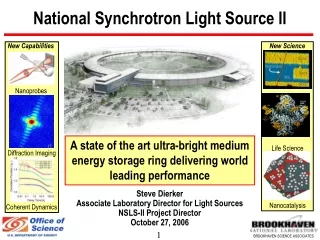
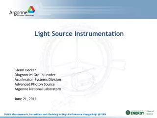
Light Source Instrumentation
Light Source Instrumentation. Glenn Decker Diagnostics Group Leader Accelerator Systems Division Advanced Photon Source Argonne National Laboratory June 21, 2011. Outline . BPM resolution / orbit stability requirements APS orbit correction hardware configuration

Light Source Instrumentation
E N D
Presentation Transcript
Light Source Instrumentation Glenn DeckerDiagnostics Group LeaderAccelerator Systems Division Advanced Photon Source Argonne National Laboratory June 21, 2011
Outline • BPM resolution / orbit stability requirements • APS orbit correction hardware configuration • Storage ring beam position monitoring technology • Lattice measurement and correction at the Advanced Photon Source • Operational resonant cavity beam position monitoring systems G. Decker - Light Source Instrumentation
Beam Stability Requirements • AC stability derived to be 5% of photon phase space dimensions* • Note that best achieved mirror slope error is a few 100 nrad. • Long-term drift limited by tunnel air and water temperature, and diffusive ground motion (ATL law)** *J. Carwardine, F. Lenkszus, G. Decker, O. Singh, “Five-Year Plan for APS Beam Stabilization” http://icmsdocs.aps.anl.gov/docs/groups/aps/documents/report/aps_1192147.pdf **Bob Lill et al., BIW 2010, Santa Fe, NM http://accelconf.web.cern.ch/AccelConf/BIW2010/papers/tupsm050.pdf, V. Shiltsev, “Review of Observations of Ground Diffusion in Space and Time and Fractal Model of Ground motion” http://prst-ab.aps.org/abstract/PRSTAB/v13/i9/e094801 G. Decker - Light Source Instrumentation
APS Orbit Correction Hardware Configuration(One of Forty Sectors) G. Decker - Light Source Instrumentation
Modern RF BPM Electronics Performance APS BSP-100 Module Libera Brilliance@APS *G. Decker, “APS Beam Stability Studies at the 100-nrad Level”, BIW10, http://accelconf.web.cern.ch/AccelConf/BIW2010/papers/tucnb02.pdf G. Decker - Light Source Instrumentation
Forward-Integrated Power Spectral Density* *Libera Brilliance+ electronics attached to 4-mm diameter capacitive pickup electrodes mounted on small-aperture (8 mm) insertion device vacuum chamber G. Decker - Light Source Instrumentation
Photoemission Blade-Type Photon Beam Position Monitors Insertion Device Gold-Plated Diamond Vertical + Horizontal Bending Magnet Molybdenum Vertical Only G. Decker - Light Source Instrumentation
APS Lattice Note: Independent control for every magnet in the machine. Qy G. Decker - Light Source Instrumentation
Response Matrix Least-Squares Fitting *J. Safranek, “Experimental determination of storage ring optics using orbit response measurements”, NIM-A 388 (1997) pp. 27-36 G. Decker - Light Source Instrumentation
Response Matrix Fitting Method – Results* *V. Sajaev, L. Emery, “Determination and Correction of the Linear Lattice of the APS Storage Ring”, EPAC 2002, http://accelconf.web.cern.ch/AccelConf/e02/PAPERS/TUPRI001.pdf G. Decker - Light Source Instrumentation
Applications based on LOCO at the Advanced Photon Source • Lattice function measurement / correction, including coupling (1% rms) • Dispersion correction • BPM gain (calibration) determination (1% rms) • Local transverse impedance determination (Sajaev, PAC2003) • Local chromaticity errors (used to find mis-wired sextupole) (Sajaev, PAC2009) • Sextupole mechanical offset determination (Sajaev, Xiao, IPAC2010 • Development / validation of new lattices in conjunction with comprehensivemachine modeling including genetic optimization over many parameters • Long straight sections (missing Q1 lattice, asymmetrically places) • Short-pulse x-ray crab cavity insertion • Increased dynamic aperture / lifetime Advanced Photon Source Upgrade (APS-U) project
Turn-by-turn diagnostics *V. Sajaev, “Use of Turn-by-turn data from FPGA-based bpms during operation of the APS storage ring, IPAC 2010 Advanced Photon Source Upgrade (APS-U) project
Lattice Determination from Model-Independent Analysis* (Principle-Component Analysis) Vertical Resonant Excitation Horizontal Sawtooth Instability One Second = 218 turns *Chun-xi Wang,V. Sajaev, C.Y. Yao, “Phase advance and beta function measurements using model-independent analysis”, prst-ab 6, 104001 (2003) G. Decker - Light Source Instrumentation
X-Band Cavity BPM Designed for LCLS G. Waldschmidt, R. Lill, L. Morrison, “Electromagnetic Design of the RF Cavity Beam Position Monitor for the LCLS PAC 2007 G. Decker - Light Source Instrumentation
X-Band Cavity BPM Designed for LCLS G. Decker - Light Source Instrumentation
Beam-Based Alignment using Cavity BPMs at LCLS *Paul Emma etal., “First Lasing of the LCLS X-ray FEL at 1.5 Angstroms”, PAC 2009, http://accelconf.web.cern.ch/AccelConf/PAC2009/papers/th3pbi01.pdf G. Decker - Light Source Instrumentation
Spring-8 XFEL C-Band Cavity BPM (Shintake) H. Maesakaetal., “DEVELOPMENT OF THE RF CAVITY BPM OF XFEL/SPRING-8” DIPAC 2009 G. Decker - Light Source Instrumentation
Summary • Sub-micron one-hour drift is now routine at light sources • Allows very accurate determination of lattice functions, BPM gains, etc. using response matrix least-squares fitting. • Large deployments of synchronous turn-by-turn bpms open up huge possibilities in terms of very accurate phase determination, non-linear dynamics studies (e.g passive amplitude-dependent tune determination) and much more. • Sub-micron single-shot capability at FEL’s allows clean beam-based alignment and stable operation. G. Decker - Light Source Instrumentation