Download
1 / 13
140 likes | 227 Views
Learn how to determine force reactions, use idealized models, and solve equilibrium problems for rigid bodies. Understand the process step by step.

E N D
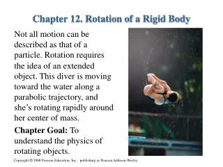
Chapter 5 EQUILIBRIUM OF A RIGID BODY
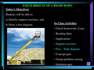
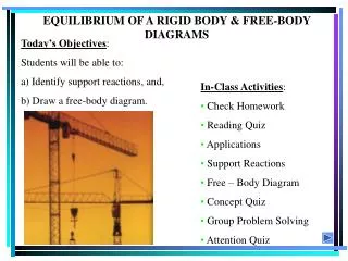
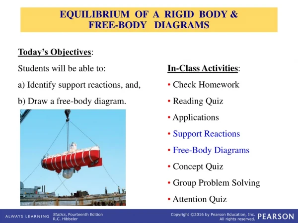
APPLICATIONS A 200 kg platform is suspended off an oil rig. How do we determine the force reactions at the joints and the forces in the cables? How are the idealized model and the free body diagram used to do this? Which diagram above is the idealized model?
APPLICATIONS (continued) A steel beam is used to support roof joists. How can we determine the support reactions at A & B? Again, how can we make use of an idealized model and a free body diagram to answer this question?
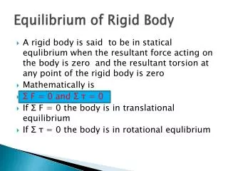
5.1 CONDITIONS FOR RIGID-BODY EQUILIBRIUM In contrast to the forces on a particle, the forces on a rigid-body are not usually concurrent and may cause rotation of the body (due to the moments created by the forces). Forces on a particle For a rigid body to be in equilibrium, the net force as well as the net moment about any arbitrary point O must be equal to zero. F = 0 and MO = 0 Forces on a rigid body
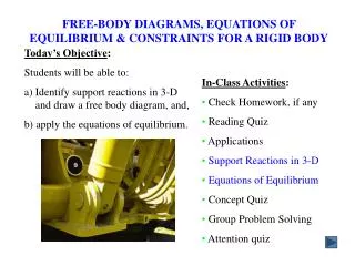
THE PROCESS OF SOLVING RIGID BODY EQUILIBRIUM PROBLEMS For analyzing an actual physical system, first we need to create an idealized model. Then we need to draw a free-body diagram showing all the external (active and reactive) forces. Finally, we need to apply the equations of equilibrium to solve for any unknowns.
5.2 FREE-BODY DIAGRAMS Free-body diagram Idealized model • 1. Draw an outlined shape. Imagine the body to be isolated or cut “free” from its constraints and draw its outlined shape. • 2. Show all the external forces and couple moments. These typically include: a) applied loads, b) support reactions, and, c) the weight of the body.
FREE-BODY DIAGRAMS (continued) Idealized model Free-body diagram • 3. Label loads and dimensions: All known forces and couple moments should be labeled with their magnitudes and directions. For the unknown forces and couple moments, use letters like Ax, Ay, MA, etc.. Indicate any necessary dimensions.
SUPPORT REACTIONS IN 2-D A few examples are shown above. Other support reactions are given in your textbook (in Table 5-1). As a general rule, if a support prevents translationof a body in a given direction, thena force is developedon the body in the opposite direction. Similarly,if rotation is prevented, a couple momentis exerted on the body.
EXAMPLE Given: An operator applies 20 lb to the foot pedal. A spring with k = 20 lb/in is stretched 1.5 in. Draw: A free-body diagram of the foot pedal. The idealized model The free-body diagram
Concept Questions 1. The beam and the cable (with a frictionless pulley at D) support an 80 kg load at C. In a FBD of only the beam, there are how many unknowns? 1) 2 forces and 1 couple moment 2) 3 forces and 1 couple moment 3) 3 forces 4) 4 forces
Concept Questions 2. If the directions of the force and the couple moments are reversed, then what will happen to the beam? A) The beam will lift from A.B) The beam will lift at B.C) The beam will be restrained. D) The beam will break.
GROUP PROBLEM SOLVING Draw a FBD of the bar, which has smooth points of contact at A, B, and C. Draw a FBD of the 5000 lb dumpster (D). It is supported by a pin at A and the hydraulic cylinder BC (treat as a short link).