Enhancing Serial Code Accelerators for Heterogeneous Multi-core Processors with 3D Memory
Explore the advancements in serial code accelerators for heterogeneous multi-core processors with 3D memory, covering topics like clock race, Amdahl's law, alternate technologies, architectural studies, FPGA core models, and thermal analysis. Discover the need for high clock rate CPUs and the challenges in improving packet handling and reducing communication latency.


Enhancing Serial Code Accelerators for Heterogeneous Multi-core Processors with 3D Memory
E N D
Presentation Transcript
Serial Code Accelerators for Heterogeneous Multi-core Processor with 3D memory Philip Jacob Thesis Defense July 26rd 2010 Committee members John F. McDonald Tong Zhang Paul Schoch Christopher D. Carothers
Outline • Need for Serial code accelerator • Clock Race • Multi-core CMOS • Amdahl’s law • Alternate technologies • SiGe /FinFET etc • ECL/ I2L • Architectural studies • HCRU CPI • Multi-core • 3D memory • Processor core and 3D memory • FPGA core model • Chip designs • Thermal Analysis • Conclusion & Future Research
Outline • Need for Serial Code Accelerator • Clock Race • Multi-core CMOS • Amdahl’s law • Alternate technologies • SiGe /FinFET etc • ECL/ I2L • Architectural studies • HCRU CPI • Multi-core • 3D memory • Processor core and 3D memory • FPGA core model • Chip designs • Thermal Analysis • Conclusion & Future Research
Motivation for High Clock Rate CPU: HPCS • Faster processing nodes to execute MPI code using SiGe HBTs. • Improve packet handling to reduce communication latency. Ref1: http://www.nas.nasa.gov/About/Projects/Columbia/columbia.html
Previous decade: Clock Race suggested need for 3D Memory Memory Wall Ref 2: Hennessey, Patterson ,”Computer Architecture – A Quantitative approach”
The Clock Race for CMOS has Ended 6 Clock Doubling Times = 64 GHz! Ref 3 : WilfriedHaensch, 2008 IBM TAPO meeting
CMOS Repeater Crisis - Wires Don’t Scale WellNumber of Repeaters is Exploding as a Power of 10 per 33% Shrink Chip Integration – Technology Challenges • Mx resistance increasing with technology scaling. • High resistance requiring increased repeater counts. • Increased power consumption as buffers are leaky and • accounts >50% of logic leakage. • Forced to reduce /hold clock rate Ref 4: RuchirPuri, IBM, 2007 Sematech/ACMThermal and Design Issues in 3D ICs
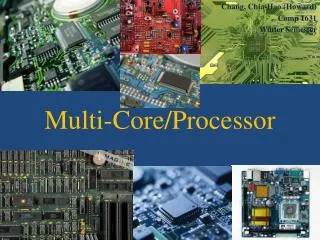
Result: Multi-cores in CMOS – Dual core to Quad Core to 50 core Generation 50 core Knights corner cloud computing chip Quad Core Dual Core
Is adding more cores the right solution? Amdahl’s 1967 Figure of Merit (FOM) estimates speedup to an overall system when only part of the system is improved.Speeding up parallel code by adding “n” cores. Ref 5:Gene Amdahl ”Validity of the single processor approach to achieving large scale computing capabilities” AFIPS Conference, 1967
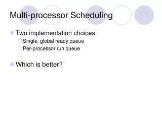
Heterogeneous Multi-core System with MCU’s, and a single HCRU for Serial Code MCU0 MCU1 • Turn off High clock rate processor • during parallel operation to save power. • Integration could be either on same chip • or through Silicon carrier. MCU2 MCU3 HCRU MCU4 MCU5 MCU6 MCU7
Outline • Need for Serial Code Accelerator • Clock Race • Multi-core CMOS • Amdahl’s law • Alternate technologies • SiGe /FinFET etc • ECL/ I2L • Architectural studies • HCRU CPI • Multi-core • 3D memory • Processor core and 3D memory • FPGA core model • Chip designs • Thermal Analysis • Conclusion & Future Research
Alternate technologies SiGe HBT Strained Si FinFETs
SiGe HBT • Vertical Device. • 3 regions of operation: OFF, Forward active, Sat. • Current equations are exponential making them better drivers of wires.
Doping Profile to form Hetero-junction • Ge into the base region reduces the potential barrier to injection of electrons from emitter into the base. • Drift field accelerates e-. • Results in increased Ic and reduced base transit time. Ref 6:On the potential of SiGe HBTs for extreme environment Electronics, Cressler, Proceedings of IEEE, Sept 2005
Scaling in SiGe HBTs • FOM- Cut off Frequency. • Solomon Tang Scaling rule. • * Circuit delay scales with emitter size. • * Shrink the Emitter for constant TOTAL Current. • Collector current density goes up. • Supply Voltage and swing voltage is constant. 90nm 130nm 180nm Ref 6: On the potential of SiGe HBTs for extreme environment Electronics, Cressler, Proceedings of IEEE, Sept 2005
Emitter Coupled Logic Design • Current Steering circuits. • Differential input/outputs. • Low voltage swings. • Taller trees for more complex gates but higher static power consumption. NAND gate
D Flip Flop Latch Cross coupled inverters
Low Power in Bipolar: I2L / Integrated Injection Logic NOR INV NAND Vcc = 1V Signal Levels Low= 0.2V High=0.7V
NPN only IIL VCC VCC Out in VEE VEE 1.1V power supply 4.4ps rise time 300mV swing In collaboration with Tuhin, Srikumar Ref 7: J.H. Pugsley and C.B. Silio, Proceeding of the 8th International Symposium of Multiple-Valued Logic, Pg 21-31, 1978
Apple Sponsored Exponential PowerPC • 0.7M Hitachi Si-bipolars. • 0.3um x 1.0 um emitter 20 GHz fT 1995. • 2.0M 0.5µm FET’s. • Die Size 15mm x 10mm. • Metal Pitch 2µm. • ~80Watts. • 0.75~0.85 GHz (last tapeout). • Mixed ECL 500mV and CML 250mV swing. • Main power supply was 3.5V (most contemporary designs would use 2.5V). 22
Outline • Need for Serial Code Accelerator • Clock Race • Multi-core CMOS • Amdahl’s law • Alternate technologies • SiGe /FinFET etc • ECL/ I2L • Architectural studies • HCRU CPI • Multi-core • 3D memory • Processor core and 3D memory • FPGA core model • Chip designs • Thermal Analysis • Conclusion & Future Research
CPI vs. Clock vs. Bus width Cache structure -unified L0 (1KB) -unified L1 (16KB) - A huge L2 - CPI=7.82 • Trace driven simulator – Dinero • Cache access time - CACTI
Access time improvement in BiCMOS over CMOS L1 cache (16K cache) 1. Decoder data 2. Word Line 3. Sense amp data 4. Comparator 5. Mux 6. Sel Inverter 7. o/p driver • CMOS access time=0.718ns • BiCMOSaccess time=0.431ns Ref 8: CACTI 4.2, 5.0 http://quid.hpl.hp.com:9081/cacti/detailed.y?new
Simplescalar – Execution driven simulator 3D cache with wide bandwidth Ref 9: www.simplescalar.com
Reducing CPI for HCRU • Simple scalar simulator • 3 level cache • SPEC int benchmarks • CPI around 2.5 to 3
3D processor memory stack solution Multi-core Multi-tier Multi-bank • Higher bandwidth through 3D-vias translates to multi-port cache accessing simultaneously multiple banks or tiers. • Good for multi-cores where bus arbitration can be avoided.
Multiprocessor simulator- RSIM Symmetric multi processor simulator adapted for 3D memory over multi-core Ref 10: RSIM http://rsim.cs.uiuc.edu/rsim/
Multi-core processor – RSIM results FFT benchmark
Outline • Need for Serial Code Accelerator • Clock Race • Multi-core CMOS • Amdahl’s law • Alternate technologies • SiGe /FinFET etc • ECL/ I2L • Architectural studies • HCRU CPI • Multi-core • 3D memory • Processor core and 3D memory • FPGA core model • Chip designs • Thermal Analysis • Conclusion & Future Research
L0 i-cache + Remote Program Counter Pipeline controller (FSM) External signals & traps Pipeline stage control signals Signals to FSM Data Reg File Instruction Decode Instruction queue Register File Stage 1 Register File Stage 2 Operand preparation ALU Output Scan Chain Core Test input (instruction sequence generator) ALU feed forward Data Bus L0 d-cache Post Ex/ Write Back Queue Update Remote PC 7 stage Pipelined processor core
Dual Ported 8HP Register File • Read Port A Operation at 18.4 GHz (measured) • 2 read ports/ 1 write port • size = 8 words Ref 11:Okan ErdogoPhd Thesis 2008
CLA carry chain test structure Measured waveform of the 8 HP adder test chip 26.67GHz Ref 12:Paul BelemjianPhd Thesis, 2008
CLOCK SET HLT STALL_CACHE STALL_BR UNSTALL_CACHE FSM X Y Z Pipe Clear States Pipe control signal Data I/p counter STAGE 1 STAGE 2 Test output Pipeline Controller FSM chip
3D FDSOI CMOS Process - MITLL Ref 13:MIT LL process documentation
3D cache – Floor plan & Microphotograph Way 0 Way 1 TAG ARRAY Way 3 Way 2 3D Via 3D Via Controller In collaboration with Aamir Zia
Measured Results of 3D memory chip Measured waveform of alternating read after write from Tier 1 at 500MHz clock Measured waveform with a string of consecutive 0s from Tier 3
SERDES 2.5w L0 d-cache (reg file) 5w L0 d-cache (reg file) 5w Adder 2.5w Write/store queue 1.4w L0 d-cache (reg file) 5w L0 d-cache (reg file) 5w Op. Prep 1w Reg File 5w Test Inst generator i-cache (Reg file) 5w FSM (Pipe line Ctrl) 1w i-cache (Reg file) 5w Inst Q 4 words 1.4w Inst Dec-oder 1w Floor planning (5mm * 5mm) L1 CACHE
Thermal Studies of Processor floor plan using COMSOL • Substrate too thick that the heat is not spreading into the bottom sink. • Deep Trench Isolation in SiGe HBT prevents lateral heat spreading 335K In collaboration with OkanErdogan
Use of Diamond Heat Spreaders View at diamond Cu boundary for 50um Diamond layer under CPU with one tier of 3D Memory Silicon thinning to 50 µm, and bonding to 50 µm diamond Ref 14:J.C. Sung et al, “Semiconductor on Diamond (SOD) for System on Chip (SoC) Architectures”, VMIC Conference, Sept. 2006, pp. 35-38.
Thermal studies with Processor- 3D memory 313K • Wafer thinning • Diamond substrate • Cu heat spreading interface layers
Outline • Need for Serial Code Accelerator • Clock Race • Multi-core CMOS • Amdahl’s law • Alternate technologies • SiGe /FinFET etc • ECL/ I2L • Architectural studies • HCRU CPI • Multi-core • 3D memory • Processor core and 3D memory • FPGA core model • Chip designs • Thermal Analysis • Conclusion & Future Research
Milestones • Fall 2004-2005 Preliminary study of 3D architecture, • 2005- 2006 DQE, IEEE D&T Paper accepted, Processor design on FPGA, MS degree • 2006-2007 Processor redesign on FPGA, Multi-core processor evaluations, Completion of course work, Candidacy • 2007-2008 Chip implementation, Testing blocks. • Operand preparation blocks • Pipeline Controller implementation in 8HP SiGe. • 2009-2010 Amdahl’s law and heterogeneous core integration • Thesis Defense
Publications • "Mitigating Memory wall effects in High clock rate and Multi-core CMOS 3D ICs- Processor Memory Stacks", Philip Jacob, Aamir Zia, Mike Chu, Jin Woo Kim, Russell Kraft, John F. McDonald, and Kerry Bernstein, Proceedings of the IEEE – 3D IC special issue. Vol.97, No.1 , Jan 2009, pp 108-122 • "Predicting the Performance of a 3D Processor-Memory Chip Stack” Philip Jacob, OkanErdogan, Aamir Zia, Paul M. Belemjian, Russell Kraft and John F. McDonald, IEEE Design and Test, Nov-Dec 2005, pp 540-547.(cited 14 times) • “A Three-Dimensional L2 cache with Ultra-Wide Data Bus for 3D Processor-Memory Integration”, Aamir Zia, Philip Jacob, Russell P. Kraft and John F. McDonald, Transactions in VLSI, IEEE. Vol. 18, No. 6, June 2010, pp 967-977. • “A 40Gs/s Time Interleaved ADC using SiGeBiCMOS technology”, Michael Chu, Philip Jacob, Jin-Woo Kim, Mitchell LeRoy, Russell Kraft, John F. McDonald, JSSC, IEEE, Vol. 45, No. 2, Feb 2010, pp 380-390. • “A Reconfigurable 40 GHz BiCMOS Uniform Delay Crossbar Switch for Broadband and Wide Tuning Range Narrowband Applications”, Jin-woo Kim, Michael Chu, Philip Jacob, Aamir Zia, Russell Kraft, John F. McDonald, IET Circuits, Devices and Systems. [Accepted]
Conclusion & Future Research goals • Need for a fast core • Possible alternative technologies especially SiGe • Chip designs in 3D memory and SiGe for processor core • Thermal analysis using COMSOL • Heterogeneous core integration with 3D memory – the way forward! • IIL Logic for low power operations • Serial code/ parallel code separation.
Thank you for your attention Questions